User login
Is Life Expectancy Different for Patients Beginning Osteoporosis Treatment?
A new trial has found that life expectancy of newly diagnosed and treated osteoporosis patients is in excess of 15 years in women younger than 75, and in men younger than 60, according to a study published online ahead of print May 21 in Journal of Bone and Mineral Research.
“How best to treat patients with osteoporosis is a really simple issue when it comes to beginning treatment, but deciding how long to treat for is really very challenging,” said lead author Bo Abrahamsen, MD, PhD, Professor and Consultant Endocrinologist at Glostrup Hospital in Copenhagen.

Researchers conducted an observational study in Danish national registries tracking prescriptions for osteoporosis drugs, comorbid conditions, and deaths. Investigators included 58,637 patients and 225,084 age- and gender-matched control subjects. Information on deaths until the end of 2013 was retrieved, providing a follow-up period of 10 to 17 years.
In men younger than 80 and women younger than 60, the relative risk of dying declined from being strongly increased in the first year to a stable but elevated level in subsequent years. In women older than 65 through 70, there was only a small elevation in risk in the first year of treatment followed by lower than background mortality.
The residual life expectancy of a 50-year-old man beginning osteoporosis treatment was estimated to be 18.2 years; for a 75-year-old man it was 7.5 years. Estimates in women were 26.4 years and 13.5 years for the same age groups, respectively.
According to the researchers, their findings show an excess mortality in men and in women below age 70 who are treated for osteoporosis, compared with the background population. This excess risk, they said, is more pronounced in the first few years on treatment. The average life expectancy of osteoporosis patients is in excess of 15 years in women below the age of 75 and in men below the age of 60, highlighting the importance of developing tools for long-term management.
“The present study shows that most of the patients we treat have a long life expectancy. Therefore it is absolutely vital that we are not complacent but develop evidence-based strategies for the long-term management of osteoporosis,” stated Dr. Abrahamsen.
Suggested Reading
Abrahamsen B, Osmond C, Cooper C. Life expectancy in patients treated for osteoporosis: observational cohort study using national Danish prescription data. J Bone Miner Res. 2015 May 21. [Epub ahead of print]
A new trial has found that life expectancy of newly diagnosed and treated osteoporosis patients is in excess of 15 years in women younger than 75, and in men younger than 60, according to a study published online ahead of print May 21 in Journal of Bone and Mineral Research.
“How best to treat patients with osteoporosis is a really simple issue when it comes to beginning treatment, but deciding how long to treat for is really very challenging,” said lead author Bo Abrahamsen, MD, PhD, Professor and Consultant Endocrinologist at Glostrup Hospital in Copenhagen.
Researchers conducted an observational study in Danish national registries tracking prescriptions for osteoporosis drugs, comorbid conditions, and deaths. Investigators included 58,637 patients and 225,084 age- and gender-matched control subjects. Information on deaths until the end of 2013 was retrieved, providing a follow-up period of 10 to 17 years.
In men younger than 80 and women younger than 60, the relative risk of dying declined from being strongly increased in the first year to a stable but elevated level in subsequent years. In women older than 65 through 70, there was only a small elevation in risk in the first year of treatment followed by lower than background mortality.
The residual life expectancy of a 50-year-old man beginning osteoporosis treatment was estimated to be 18.2 years; for a 75-year-old man it was 7.5 years. Estimates in women were 26.4 years and 13.5 years for the same age groups, respectively.
According to the researchers, their findings show an excess mortality in men and in women below age 70 who are treated for osteoporosis, compared with the background population. This excess risk, they said, is more pronounced in the first few years on treatment. The average life expectancy of osteoporosis patients is in excess of 15 years in women below the age of 75 and in men below the age of 60, highlighting the importance of developing tools for long-term management.
“The present study shows that most of the patients we treat have a long life expectancy. Therefore it is absolutely vital that we are not complacent but develop evidence-based strategies for the long-term management of osteoporosis,” stated Dr. Abrahamsen.
Suggested Reading
Abrahamsen B, Osmond C, Cooper C. Life expectancy in patients treated for osteoporosis: observational cohort study using national Danish prescription data. J Bone Miner Res. 2015 May 21. [Epub ahead of print]
Suggested Reading
Abrahamsen B, Osmond C, Cooper C. Life expectancy in patients treated for osteoporosis: observational cohort study using national Danish prescription data. J Bone Miner Res. 2015 May 21. [Epub ahead of print]

Investigational Osteoporosis Drug Lowers Fracture Risk
Abaloparatide-SC, an injectable drug being studied for the treatment of postmenopausal osteoporosis, reduces the rate of new spinal fractures by 86%, as well as provide statistically significant reductions in the fracture rate at other parts of the body, according to data from the phase 3 ACTIVE fracture prevention trial (ACTIVE trial). Results from the ACTIVE trial were reported at the Endocrine Society’s 97th Annual Meeting in San Diego.
“The investigational drug abaloparatide-SC, if approved, may offer patients the potential to reduce their risk of fracture and increase bone density at all sites, even the most difficult to treat, such as the hip and wrist,” said lead investigator Paul Miller, MD, Medical Director of the Colorado Center for Bone Research in Lakewood.

Abaloparatide-SC is a new manmade form of human parathyroid hormone-related protein that is manufactured by Radius Health (Waltham, Massachusetts). The drugmaker is studying the medication in various forms, including a transdermal patch, in addition to the subcutaneous injection studied in the ACTIVE trial.
During the ACTIVE trial, researchers studied whether abaloparatide-SC can reduce fractures in postmenopausal women with severe osteoporosis who have a high fracture risk. The investigators compared rates of new fractures in 690 women who received a daily injection of abaloparatide-SC (80 mcg) and 711 women who received inactive placebo shots. Neither group of women knew which treatment they received. A third group of 717 women received a daily injection of teriparatide (20 mcg) in an unblinded fashion. All patients also received calcium and vitamin D supplements.
Over 18 months of treatment, the abaloparatide-SC-treated group had the greatest reduction in the rate of new vertebral fractures shown on x-ray, Dr. Miller reported. Compared with the placebo group’s new vertebral fracture rate of 4.2%, women who were treated with abaloparatide-SC had a new vertebral fracture rate of about 0.58%, representing an 86% reduction in the rate of broken bones at the spine, according to Dr. Miller.
“We believe this reduction seen in the abaloparatide-SC-treated group could be the largest reduction ever demonstrated in the vertebral fracture rate for any potential therapeutic drug being researched for the treatment of postmenopausal osteoporosis,” Dr. Miller said.
For nonvertebral fractures, Dr. Miller said abaloparatide-SC treatment had a 43% fracture-rate reduction compared to that of placebo. The rate of vertebral and nonvertebral fractures combined decreased by 45% in the abaloparatide-SC-treated group versus the placebo group. Additionally, the time to the first nonvertebral fracture was significantly delayed for women receiving abaloparatide-SC than for those who received a placebo, he said.
Results of patients’ bone mineral density tests also were compared between the two drug treatment groups. “Abaloparatide-SC resulted in more bone growth, at a faster rate, at more skeletal sites, and in more patients than teriparatide,” stated Dr. Miller.
Abaloparatide-SC, an injectable drug being studied for the treatment of postmenopausal osteoporosis, reduces the rate of new spinal fractures by 86%, as well as provide statistically significant reductions in the fracture rate at other parts of the body, according to data from the phase 3 ACTIVE fracture prevention trial (ACTIVE trial). Results from the ACTIVE trial were reported at the Endocrine Society’s 97th Annual Meeting in San Diego.
“The investigational drug abaloparatide-SC, if approved, may offer patients the potential to reduce their risk of fracture and increase bone density at all sites, even the most difficult to treat, such as the hip and wrist,” said lead investigator Paul Miller, MD, Medical Director of the Colorado Center for Bone Research in Lakewood.
Abaloparatide-SC is a new manmade form of human parathyroid hormone-related protein that is manufactured by Radius Health (Waltham, Massachusetts). The drugmaker is studying the medication in various forms, including a transdermal patch, in addition to the subcutaneous injection studied in the ACTIVE trial.
During the ACTIVE trial, researchers studied whether abaloparatide-SC can reduce fractures in postmenopausal women with severe osteoporosis who have a high fracture risk. The investigators compared rates of new fractures in 690 women who received a daily injection of abaloparatide-SC (80 mcg) and 711 women who received inactive placebo shots. Neither group of women knew which treatment they received. A third group of 717 women received a daily injection of teriparatide (20 mcg) in an unblinded fashion. All patients also received calcium and vitamin D supplements.
Over 18 months of treatment, the abaloparatide-SC-treated group had the greatest reduction in the rate of new vertebral fractures shown on x-ray, Dr. Miller reported. Compared with the placebo group’s new vertebral fracture rate of 4.2%, women who were treated with abaloparatide-SC had a new vertebral fracture rate of about 0.58%, representing an 86% reduction in the rate of broken bones at the spine, according to Dr. Miller.
“We believe this reduction seen in the abaloparatide-SC-treated group could be the largest reduction ever demonstrated in the vertebral fracture rate for any potential therapeutic drug being researched for the treatment of postmenopausal osteoporosis,” Dr. Miller said.
For nonvertebral fractures, Dr. Miller said abaloparatide-SC treatment had a 43% fracture-rate reduction compared to that of placebo. The rate of vertebral and nonvertebral fractures combined decreased by 45% in the abaloparatide-SC-treated group versus the placebo group. Additionally, the time to the first nonvertebral fracture was significantly delayed for women receiving abaloparatide-SC than for those who received a placebo, he said.
Results of patients’ bone mineral density tests also were compared between the two drug treatment groups. “Abaloparatide-SC resulted in more bone growth, at a faster rate, at more skeletal sites, and in more patients than teriparatide,” stated Dr. Miller.

Osteoporosis Diagnosis Linked to Increased Risk of Hearing Loss?
Patients who have osteoporosis face a 1.76-fold higher risk of developing sudden sensorineural hearing loss (SSHL) than those who do not have the bone disease, according to a study published online ahead of print April 16 in the Journal of Clinical Endocrinology & Metabolism.
“A growing body of evidence indicates that osteoporosis affects not only bone health, but the cardiovascular and cerebrovascular systems,” said study author Kai-Jen Tien, MD, from the Chi Mei Medical Center in Taiwan.

SSHL, also called sudden deafness, is an unexplained, rapid loss of hearing that typically happens in one ear, according to the National Institute on Deafness and Other Communication Disorders. It can happen at once or over the course of several days. Although about half of the people who develop SSHL will spontaneously regain their hearing, immediate treatment is recommended. About 85% of those who are treated for the condition recover some hearing.
This retrospective cohort study examined medical records for 10,660 Taiwan residents who were diagnosed with osteoporosis between 1999 and 2008, and compared them to 31,980 controls who did not have the condition. Using national insurance records, the researchers analyzed how many participants were diagnosed with sudden deafness by the end of 2011.
The participants who were diagnosed with osteoporosis had a much higher risk of developing SSHL than the control group. Among the participants who had osteoporosis, 91 were diagnosed with SSHL during the follow-up period. In comparison, the control group, which was triple the size, included 155 people who were diagnosed with SSHL.
Dr. Tien and colleagues theorized that cardiovascular risk factors, bone demineralization, inflammation, and endothelial dysfunction may contribute to the association between osteoporosis and SSHL.
“More people worldwide are suffering from osteoporosis, and our work shows they are at risk of sensorineural hearing loss, as well as bone fracture and other problems,” Dr. Tien said. “Patients who have osteoporosis should be aware they need to seek medical help immediately if they experience hearing loss.”
Dr. Tien stated, “Our findings suggest sudden sensorineural hearing loss can be another broader health problem connected to osteoporosis.”
Suggested Reading
Yeh MC, Weng SF, Shen YC, et al. Increased risk of sudden sensorineural hearing loss in patients with osteoporosis: a population-based, propensity score-matched, longitudinal follow-up study. J Clin Endocrinol Metab. 2015 Apr 16:jc20144316. [Epub ahead of print]
Patients who have osteoporosis face a 1.76-fold higher risk of developing sudden sensorineural hearing loss (SSHL) than those who do not have the bone disease, according to a study published online ahead of print April 16 in the Journal of Clinical Endocrinology & Metabolism.
“A growing body of evidence indicates that osteoporosis affects not only bone health, but the cardiovascular and cerebrovascular systems,” said study author Kai-Jen Tien, MD, from the Chi Mei Medical Center in Taiwan.
SSHL, also called sudden deafness, is an unexplained, rapid loss of hearing that typically happens in one ear, according to the National Institute on Deafness and Other Communication Disorders. It can happen at once or over the course of several days. Although about half of the people who develop SSHL will spontaneously regain their hearing, immediate treatment is recommended. About 85% of those who are treated for the condition recover some hearing.
This retrospective cohort study examined medical records for 10,660 Taiwan residents who were diagnosed with osteoporosis between 1999 and 2008, and compared them to 31,980 controls who did not have the condition. Using national insurance records, the researchers analyzed how many participants were diagnosed with sudden deafness by the end of 2011.
The participants who were diagnosed with osteoporosis had a much higher risk of developing SSHL than the control group. Among the participants who had osteoporosis, 91 were diagnosed with SSHL during the follow-up period. In comparison, the control group, which was triple the size, included 155 people who were diagnosed with SSHL.
Dr. Tien and colleagues theorized that cardiovascular risk factors, bone demineralization, inflammation, and endothelial dysfunction may contribute to the association between osteoporosis and SSHL.
“More people worldwide are suffering from osteoporosis, and our work shows they are at risk of sensorineural hearing loss, as well as bone fracture and other problems,” Dr. Tien said. “Patients who have osteoporosis should be aware they need to seek medical help immediately if they experience hearing loss.”
Dr. Tien stated, “Our findings suggest sudden sensorineural hearing loss can be another broader health problem connected to osteoporosis.”
Suggested Reading
Yeh MC, Weng SF, Shen YC, et al. Increased risk of sudden sensorineural hearing loss in patients with osteoporosis: a population-based, propensity score-matched, longitudinal follow-up study. J Clin Endocrinol Metab. 2015 Apr 16:jc20144316. [Epub ahead of print]
Suggested Reading
Yeh MC, Weng SF, Shen YC, et al. Increased risk of sudden sensorineural hearing loss in patients with osteoporosis: a population-based, propensity score-matched, longitudinal follow-up study. J Clin Endocrinol Metab. 2015 Apr 16:jc20144316. [Epub ahead of print]

Young Patients Who Undergo ACL Surgery May Drastically Improve Physical Health and Function
Most patients who underwent surgery to repair and rebuild an anterior cruciate ligament (ACL) tear showed significant improvement in physical function at 2 years, which continued for at least 6 years following surgery, according to a study published April 1 in the Journal of Bone & Joint Surgery. Younger patient age, lower body mass index, and having the remnants of the torn ACL completely excised during surgery were among the strongest predictors of positive, long-term outcome.
In this study, researchers reviewed and evaluated the outcomes of 1,411 patients (44% female; average patient age at enrollment, 23) who underwent ACL surgery between 2002 and 2004 at four major medical centers. Each patient completed questionnaires that assessed health, well-being, and function prior to surgery, and again at 2 and 6 years after surgery.
“We found that health-related quality of life was significantly improved following ACL reconstruction, and this improvement was still present 6 years following surgery,” said lead study author Warren R. Dunn, MD, MPH, an orthopedic surgeon at the University of Wisconsin in Madison.

At baseline, the average physical health score was 41.9 and the mean mental health score was 51.7. At 2 years after surgery, the physical and mental health scores were stable at 53.6 and 52 points, respectively, and 54 and 52.4 points at year 6.
Among the study’s findings:
• ACL reconstruction resulted in large improvements in the physical function scores, with a mean improvement of 12 points (out of 100) at 2 years and 6 years following surgery.
• At 6 years following ACL surgery, patients gained a mean 5.3 quality-adjusted life years.
• Baseline activity level was a significant predictor of mental health scores, but not physical function scores.
• Predictors of worse postoperative outcomes were a shorter follow-up time post-surgery, revision ACL reconstruction, smoking at baseline, fewer years of education, and damage to the cartilage under the chondromalacia patella.
• Physical function continued to improve over the long term following reconstruction. Patients requiring a revision reconstruction did not fare as well as patients undergoing a single reconstruction.
• Mental health scores over the 6-year period did not significantly change, but scores consistently remained above the population norm of 50 points.
“The predictors for good and poorer outcomes may be helpful when counseling patients who are considering ACL surgery,” stated Dr. Dunn.
Suggested Reading
Dunn WR, Wolf BR, Harrell FE Jr, et al. Baseline predictors of health-related quality of life after anterior cruciate ligament reconstruction: a longitudinal analysis of a multicenter cohort at two and six years. J Bone Joint Surg Am. 2015;97(7):551-557.
Most patients who underwent surgery to repair and rebuild an anterior cruciate ligament (ACL) tear showed significant improvement in physical function at 2 years, which continued for at least 6 years following surgery, according to a study published April 1 in the Journal of Bone & Joint Surgery. Younger patient age, lower body mass index, and having the remnants of the torn ACL completely excised during surgery were among the strongest predictors of positive, long-term outcome.
In this study, researchers reviewed and evaluated the outcomes of 1,411 patients (44% female; average patient age at enrollment, 23) who underwent ACL surgery between 2002 and 2004 at four major medical centers. Each patient completed questionnaires that assessed health, well-being, and function prior to surgery, and again at 2 and 6 years after surgery.
“We found that health-related quality of life was significantly improved following ACL reconstruction, and this improvement was still present 6 years following surgery,” said lead study author Warren R. Dunn, MD, MPH, an orthopedic surgeon at the University of Wisconsin in Madison.
At baseline, the average physical health score was 41.9 and the mean mental health score was 51.7. At 2 years after surgery, the physical and mental health scores were stable at 53.6 and 52 points, respectively, and 54 and 52.4 points at year 6.
Among the study’s findings:
• ACL reconstruction resulted in large improvements in the physical function scores, with a mean improvement of 12 points (out of 100) at 2 years and 6 years following surgery.
• At 6 years following ACL surgery, patients gained a mean 5.3 quality-adjusted life years.
• Baseline activity level was a significant predictor of mental health scores, but not physical function scores.
• Predictors of worse postoperative outcomes were a shorter follow-up time post-surgery, revision ACL reconstruction, smoking at baseline, fewer years of education, and damage to the cartilage under the chondromalacia patella.
• Physical function continued to improve over the long term following reconstruction. Patients requiring a revision reconstruction did not fare as well as patients undergoing a single reconstruction.
• Mental health scores over the 6-year period did not significantly change, but scores consistently remained above the population norm of 50 points.
“The predictors for good and poorer outcomes may be helpful when counseling patients who are considering ACL surgery,” stated Dr. Dunn.
Suggested Reading
Dunn WR, Wolf BR, Harrell FE Jr, et al. Baseline predictors of health-related quality of life after anterior cruciate ligament reconstruction: a longitudinal analysis of a multicenter cohort at two and six years. J Bone Joint Surg Am. 2015;97(7):551-557.
Suggested Reading
Dunn WR, Wolf BR, Harrell FE Jr, et al. Baseline predictors of health-related quality of life after anterior cruciate ligament reconstruction: a longitudinal analysis of a multicenter cohort at two and six years. J Bone Joint Surg Am. 2015;97(7):551-557.

Rationale for Strategic Graft Placement in Anterior Cruciate Ligament Reconstruction: I.D.E.A.L. Femoral Tunnel Position
In the United States, surgeons perform an estimated 200,000 anterior cruciate ligament reconstructions (ACLRs) each year. Over the past decade, there has been a surge in interest in defining anterior cruciate ligament (ACL) anatomy to guide ACLR. With this renewed interest in the anatomical features of the ACL, particularly the insertion site, many authors have advocated an approach for complete or near-complete “footprint restoration” for anatomical ACLR.1,2 Some have recommended a double-bundle (DB) technique that completely “fills” the footprint, but it is seldom used. Others have proposed centralizing the femoral tunnel position within the ACL footprint in the hope of capturing the function of both the anteromedial (AM) and posterolateral (PL) bundles.1,3,4 Indeed, a primary surgical goal of most anatomical ACLR techniques is creation of a femoral tunnel based off the anatomical centrum (center point) of the ACL femoral footprint.3,5 With a single-bundle technique, the femoral socket is localized in the center of the entire footprint; with a DB technique, sockets are created in the centrums of both the AM and PL bundles.
Because of the complex shape of the native ACL, however, the strategy of restoring the femoral footprint with use of either a central tunnel or a DB approach has been challenged. The femoral footprint is 3.5 times larger than the midsubstance of the ACL.6 Detailed anatomical dissections have recently demonstrated that the femoral origin of the ACL has a stout anterior band of fibers with a fanlike extension posteriorly.7 As the ACL fibers extend off the bony footprint, they form a flat, ribbonlike structure 9 to 16 mm wide and only 2 to 4 mm thick.2,8 Within this structure, there is no clear separation of the AM and PL bundles. The presence of this structure makes sense given the anatomical constraints inherent in the notch. Indeed, the space for the native ACL is narrow, as the posterior cruciate ligament (PCL) occupies that largest portion of the notch with the knee in full extension, leaving only a thin, 5-mm slot through which the ACL must pass.9 Therefore, filling the femoral footprint with a tubular ACL graft probably does not reproduce the dynamic 3-dimensional morphology of the ACL.
In light of the discrepancy between the sizes of the femoral footprint and the midsubstance of the native ACL, it seems reasonable that optimizing the position of the ACL femoral tunnel may be more complex than simply centralizing the tunnel within the footprint or attempting to maximize footprint coverage. In this article, we amalgamate the lessons of 4 decades of ACL research into 5 points for strategic femoral tunnel positioning, based on anatomical, histologic, isometric, biomechanical, and clinical data. These points are summarized by the acronym I.D.E.A.L., which refers to placing a femoral tunnel in a position that reproduces the Isometry of the native ACL, that covers the fibers of the Direct insertion histologically, that is Eccentrically located in the anterior (high) and proximal (deep) region of the footprint, that is Anatomical (within the footprint), and that replicates the Low tension-flexion pattern of the native ACL throughout the range of flexion and extension.
1. Anatomy Considerations
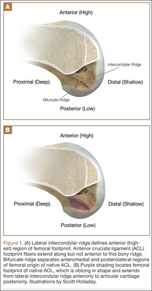
In response to study results demonstrating that some transtibial ACLRs were associated with nonanatomical placement of the femoral tunnel—resulting in vertical graft placement, PCL impingement, and recurrent rotational instability10-16—investigators have reexamined both the anatomy of the femoral origin of the native ACL and the ACL graft. Specifically, a large body of research has been devoted to characterizing the osseous landmarks of the femoral origin of the ACL17 and the dimensions of the femoral footprint.3 In addition, authors have supported the concept that the ACL contains 2 functional bundles, AM and PL.5,17 Several osseous landmarks have been identified as defining the boundaries of the femoral footprint. The lateral intercondylar ridge is the most anterior aspect of the femoral footprint and was first defined by Clancy.18 More recently, the lateral bifurcate ridge, which separates the AM and PL bundle insertion sites, was described19 (Figure 1A).
These osseous ridges delineate the location of the femoral footprint. Studies have shown that ACL fibers attach from the lateral intercondylar ridge on the anterior border of the femoral footprint and extend posteriorly to the cartilage of the lateral femoral condyle (Figure 1B).
ACL fibers from this oblong footprint are organized such that the midsubstance of the ACL is narrower than the femoral footprint. Anatomical dissections have demonstrated that, though the femoral footprint is oval, the native ACL forms a flat, ribbonlike structure 9 to 16 mm wide and only 2 to 4 mm thick as it takes off from the bone.8,20 There is a resulting discrepancy between the femoral footprint size and shape and the morphology of the native ACL, and placing a tunnel in the center of the footprint or “filling the footprint” with ACL graft may not reproduce the morphology or function of the native ACL. Given this size mismatch, strategic decisions need to be made to place the femoral tunnel in a specific region of the femoral footprint to optimize its function.
2. Histologic Findings
Histologic analysis has further clarified the relationship between the femoral footprint and functional aspects of the native ACL. The femoral origin of the ACL has distinct direct and indirect insertions, as demonstrated by histology and 3-dimensional volume-rendered computed tomography.21 The direct insertion consists of dense collagen fibers anterior in the footprint that is attached to a bony depression immediately posterior to the lateral intercondylar ridge.19 Sasaki and colleagues22 found that these direct fibers extended a mean (SD) of 5.3 (1.1) mm posteriorly but did not continue to the posterior femoral articular cartilage. The indirect insertion consists of more posterior collagen fibers that extend to and blend into the articular cartilage of the posterior aspect of the lateral femoral condyle. Mean (SD) width of this membrane-like tissue, located between the direct insertion and the posterior femoral articular cartilage, was found by Sasaki and colleagues22 to be 4.4 (0.5) mm anteroposteriorly(Figure 2). This anterior band of ACL tissue with the direct insertion histologically corresponds to the fibers in the anterior, more isometric region of the femoral footprint. Conversely, the more posterior band of fibers with its indirect insertion histologically corresponds to the more anisometric region and is seen macroscopically as a fanlike projection extending to the posterior articular cartilage.7

The dense collagen fibers of the direct insertion and the more membrane-like indirect insertion regions of the femoral footprint of the native ACL suggest that these regions have different load-sharing characteristics. The direct fibers of the insertion form a firm, fixed attachment that allows for gradual load distribution into the subchondral bone. From a biomechanical point of view, this attachment is extremely important, a key ligament–bone link transmitting mechanical load to the joint.23 A recent kinematic analysis revealed that the indirect fibers in the posterior region of the footprint, adjacent to the posterior articular cartilage, contribute minimally to restraint of tibial translation and rotations during stability examination.24 This suggests it may be strategically wise to place a tunnel in the direct insertion region of the footprint—eccentrically anterior (high) in the footprint rather than in the centrum.
3. Isometric Considerations
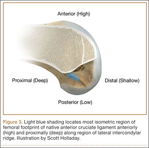
Forty years ago, Artmann and Wirth25 reported that a nearly isometric region existed in the femur such that there is minimal elongation of the native ACL during knee motion. The biomechanical rationale for choosing an isometric region of an ACL graft is that it will maintain function throughout the range of flexion and extension. A nonisometric graft would be expected to slacken during a large portion of the flexion cycle and not restrain anterior translation of the tibia, or, if fixed at the wrong flexion angle, it could capture the knee and cause graft failure by excessive tension. These 2 theoretical undesirable effects from nonisometric graft placement are supported by many experimental and clinical studies demonstrating that nonisometric femoral tunnel placement at time of surgery can cause recurrent anterior laxity of the knee.26-28 Multiple studies have further clarified that the isometric characteristics of an ACL graft are largely determined by femoral positioning. The most isometric region of the femoral footprint is consistently shown to be localized eccentrically within the footprint, in a relatively narrow bandlike region that is proximal (deep) and anterior (along the lateral intercondylar ridge within the footprint)19,29,30 (Figure 3).
A large body of literature has demonstrated that a tunnel placed in the center of the femoral footprint is less isometric than a tunnel in the more anterior region.25,29,31,32 Indeed, the anterior position (high in the footprint) identified by Hefzy and colleagues29 demonstrated minimal anisometry with 1 to 4 mm of length change through the range of motion. In contrast, a central tunnel would be expected to demonstrate 5 to 7 mm of length change, whereas a lower graft (in the PL region of the footprint) would demonstrate about 1 cm of length change through the range of motion.31,32 As such, central grafts, or grafts placed in the PL portion of the femoral footprint, would be expected to see high tension or graft forces as the knee is flexed, or to lose tension completely if the graft is fixed at full extension.32
Importantly, Markolf and colleagues33 reported that the native ACL does not behave exactly in a so-called isometric fashion during the last 30° of extension. They showed that about 3 mm of retraction of a trial wire into the joint during the last 30° of extension (as measured with an isometer) is reasonable to achieve graft length changes approximating those of the intact ACL. Given this important caveat, a primary goal for ACLR is placement of the femoral tunnel within this isometric region so that the length change in the ACL graft is minimized to 3 mm from 30° to full flexion. In addition, results of a time-zero biomechanical study suggested better rotational control with anatomical femoral tunnel position than with an isometric femoral tunnel34 placed outside the femoral footprint. Therefore, maximizing isometry alone is not the goal; placing the graft in the most isometric region within the anatomical femoral footprint is desired. This isometric region in the footprint is in the histologic region that corresponds to the direct fibers. Again, this region is eccentrically located in the anterior (high) and proximal (deep) portion of the footprint.
4. Biomechanical Considerations
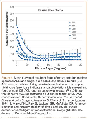
Multiple cadaveric studies have investigated the relationship between femoral tunnel positioning and time-zero stability. These studies often demonstrated superior time-zero control of knee stability, particularly in pivot type maneuvers, with a femoral tunnel placed more centrally in the femoral footprint than with a tunnel placed outside the footprint.34-37 However, an emerging body of literature is finding no significant difference in time-zero stability between an anteriorly placed femoral tunnel within the anatomical footprint (eccentrically located in the footprint) and a centrally placed graft.38,39 Returning to the more isometric tunnel position, still within the femoral footprint, would be expected to confer the benefits of an anatomically based graft position with the advantageous profile of improved isometry, as compared with a centrally placed or PL graft. Biomechanical studies40 have documented that ACL graft fibers placed posteriorly (low) in the footprint cause high graft forces in extension and, in some cases, graft rupture (Figure 4). Accordingly, the importance of reconstructing the posterior region of the footprint to better control time-zero stability is questioned.41
In addition to time-zero control of the stability examination, restoring the low tension-flexion pattern in the ACL graft to replicate the tension-flexion behavior of the native ACL is a fundamental biomechanical principle of ACLR.15,33,42,43 These studies have demonstrated that a femoral tunnel localized anterior (high) and proximal (deep) within the footprint better replicates the tension-flexion behavior of the native ACL, as compared with strategies that attempt to anatomically “fill the footprint.”40 Together, these studies have demonstrated that an eccentric position in the footprint, in the anterior (high) and proximal (deep) region, not only maximizes isometry and restores the direct fibers, but provides favorable time-zero stability and a low tension-flexion pattern biomechanically, particularly as compared with a tunnel in the more central or posterior region of the footprint.
5. Clinical Data
Clinical studies of the traditional transtibial ACLR have shown good results.44,45 However, when the tibial tunnel in the coronal plane was drilled vertical with respect to the medial joint line of the tibia, the transtibially placed femoral tunnel migrated anterior to the anatomical femoral footprint, often on the roof of the notch.10,14 This nonanatomical, vertical placement of the femoral tunnel led to failed normalization of knee kinematics.46-50 Indeed, a higher tension-flexion pattern was found in this nonanatomical “roof” position for the femoral tunnel as compared with the native ACL—a pattern that can result in either loss of flexion or recurrent instability.13,15,51
Clinical results of techniques used to create an anatomical ACLR centrally within the footprint have been mixed. Registry data showed that the revision rate at 4 years was higher with the AM portal technique (5.16%) than with transtibial drilling (3.20%).52 This higher rate may be associated with the more central placement of the femoral tunnel with the AM portal technique than with the transtibial technique, as shown in vivo with high-resolution magnetic resonance imaging.12 Recent reports have documented a higher rate of failure with DB or central ACLR approaches than with traditional transtibial techniques.53 As mentioned, in contrast to a more isometric position, a central femoral tunnel position would be expected to demonstrate 5 to 7 mm of length change, whereas moving the graft more posterior in the footprint (closer to the articular cartilage) would result in more than 1 cm of length change through the range of motion.31,32 As such, these more central grafts, or grafts placed even lower (more posterior) in the footprint, would be expected to see high tension in extension (if fixed in flexion), or to lose tension completely during flexion (if the graft is fixed at full extension).32 This may be a mechanistic cause of the high failure rate in the more posterior bundles of the DB approach.54
Together, these clinical data suggest that the femoral tunnel should be placed within the anatomical footprint of the ACL. However, within the footprint, a more eccentric femoral tunnel position capturing the isometric and direct region of the insertion may be preferable to a more central or posterior (low region) position.
Summary
Anatomical, histologic, isometric, biomechanical, and clinical data from more than 4 decades collectively point to an optimal position for the femoral tunnel within the femoral footprint. This position can be summarized by the acronym I.D.E.A.L., which refers to placing a femoral tunnel in a position that reproduces the Isometry of the native ACL, that covers the fibers of the Direct insertion histologically, that is Eccentrically located in the anterior (high) and proximal (deep) region of the footprint, that is Anatomical (within the footprint), and that replicates the Low tension-flexion pattern of the native ACL throughout the range of flexion and extension (Figure 5).
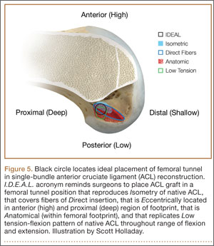
In vivo and in vitro studies as well as surgical experience suggest a need to avoid both (a) the nonanatomical vertical (roof) femoral tunnel placement that causes PCL impingement, high tension in the ACL graft in flexion, and ultimately graft stretch-out with instability and (b) the femoral tunnel placement in the posterior (lowest) region of the footprint that causes high tension in extension and can result in graft stretch-out with instability.13,15,39,40 The transtibial and AM portal techniques can both be effective in properly placing the femoral tunnel and restoring motion, stability, and function to the knee. Their effectiveness, however, depends on correct placement of the femoral tunnel. We think coming studies will focus on single-bundle ACLR and will be designed to improve the reliability of the transtibial and AM portal techniques for placing a femoral tunnel in keeping with the principles summarized by the I.D.E.A.L. acronym.
1. Siebold R. The concept of complete footprint restoration with guidelines for single- and double-bundle ACL reconstruction. Knee Surg Sports Traumatol Arthrosc. 2011;19(5):699-706.
2. Siebold R, Schuhmacher P. Restoration of the tibial ACL footprint area and geometry using the modified insertion site table. Knee Surg Sports Traumatol Arthrosc. 2012;20(9):1845-1849.
3. Piefer JW, Pflugner TR, Hwang MD, Lubowitz JH. Anterior cruciate ligament femoral footprint anatomy: systematic review of the 21st century literature. Arthroscopy. 2012;28(6):872-881.
4. Wilson AJ, Yasen SK, Nancoo T, Stannard R, Smith JO, Logan JS. Anatomic all-inside anterior cruciate ligament reconstruction using the translateral technique. Arthrosc Tech. 2013;2(2):e99-e104.
5. Colombet P, Robinson J, Christel P, et al. Morphology of anterior cruciate ligament attachments for anatomic reconstruction: a cadaveric dissection and radiographic study. Arthroscopy. 2006;22(9):984-992.
6. Harner CD, Baek GH, Vogrin TM, Carlin GJ, Kashiwaguchi S, Woo SL. Quantitative analysis of human cruciate ligament insertions. Arthroscopy. 1999;15(7):741-749.
7. Mochizuki T, Fujishiro H, Nimura A, et al. Anatomic and histologic analysis of the mid-substance and fan-like extension fibres of the anterior cruciate ligament during knee motion, with special reference to the femoral attachment. Knee Surg Sports Traumatol Arthrosc. 2014;22(2):336-344.
8. Siebold R, Schuhmacher P, Fernandez F, et al. Flat midsubstance of the anterior cruciate ligament with tibial “C”-shaped insertion site [published correction appears in Knee Surg Sports Traumatol Arthrosc. 2014 Aug 23. Epub ahead of print]. Knee Surg Sports Traumatol Arthrosc. 2014 May 20. [Epub ahead of print]
9. Triantafyllidi E, Paschos NK, Goussia A, et al. The shape and the thickness of the anterior cruciate ligament along its length in relation to the posterior cruciate ligament: a cadaveric study. Arthroscopy. 2013;29(12):1963-1973.
10. Arnold MP, Kooloos J, van Kampen A. Single-incision technique misses the anatomical femoral anterior cruciate ligament insertion: a cadaver study. Knee Surg Sports Traumatol Arthrosc. 2001;9(4):194-199.
11. Ayerza MA, Múscolo DL, Costa-Paz M, Makino A, Rondón L. Comparison of sagittal obliquity of the reconstructed anterior cruciate ligament with native anterior cruciate ligament using magnetic resonance imaging. Arthroscopy. 2003;19(3):257-261.
12. Bowers AL, Bedi A, Lipman JD, et al. Comparison of anterior cruciate ligament tunnel position and graft obliquity with transtibial and anteromedial portal femoral tunnel reaming techniques using high-resolution magnetic resonance imaging. Arthroscopy. 2011;27(11):1511-1522.
13. Howell SM, Gittins ME, Gottlieb JE, Traina SM, Zoellner TM. The relationship between the angle of the tibial tunnel in the coronal plane and loss of flexion and anterior laxity after anterior cruciate ligament reconstruction. Am J Sports Med. 2001;29(5):567-574.
14. Kopf S, Forsythe B, Wong AK, et al. Nonanatomic tunnel position in traditional transtibial single-bundle anterior cruciate ligament reconstruction evaluated by three-dimensional computed tomography. J Bone Joint Surg Am. 2010;92(6):1427-1431.
15. Simmons R, Howell SM, Hull ML. Effect of the angle of the femoral and tibial tunnels in the coronal plane and incremental excision of the posterior cruciate ligament on tension of an anterior cruciate ligament graft: an in vitro study. J Bone Joint Surg Am. 2003;85(6):1018-1029.
16. Stanford FC, Kendoff D, Warren RF, Pearle AD. Native anterior cruciate ligament obliquity versus anterior cruciate ligament graft obliquity: an observational study using navigated measurements. Am J Sports Med. 2009;37(1):114-119.
17. Ferretti M, Ekdahl M, Shen W, Fu FH. Osseous landmarks of the femoral attachment of the anterior cruciate ligament: an anatomic study. Arthroscopy. 2007;23(11):1218-1225.
18. Hutchinson MR, Ash SA. Resident’s ridge: assessing the cortical thickness of the lateral wall and roof of the intercondylar notch. Arthroscopy. 2003;19(9):931-935.
19. Fu FH, Jordan SS. The lateral intercondylar ridge—a key to anatomic anterior cruciate ligament reconstruction. J Bone Joint Surg Am. 2007;89(10):2103-2104.
20. Smigielski R, Zdanowicz U, Drwięga M, Ciszek B, Ciszkowska-Łysoń B, Siebold R. Ribbon like appearance of the midsubstance fibres of the anterior cruciate ligament close to its femoral insertion site: a cadaveric study including 111 knees. Knee Surg Sports Traumatol Arthrosc. 2014 Jun 28. [Epub ahead of print]
21. Iwahashi T, Shino K, Nakata K, et al. Direct anterior cruciate ligament insertion to the femur assessed by histology and 3-dimensional volume-rendered computed tomography. Arthroscopy. 2010;26(9 suppl):S13-S20.
22. Sasaki N, Ishibashi Y, Tsuda E, et al. The femoral insertion of the anterior cruciate ligament: discrepancy between macroscopic and histological observations. Arthroscopy. 2012;28(8):1135-1146.
23. Benjamin M, Moriggl B, Brenner E, Emery P, McGonagle D, Redman S. The “enthesis organ” concept: why enthesopathies may not present as focal insertional disorders. Arthritis Rheum. 2004;50(10):3306-3313.
24. Pathare NP, Nicholas SJ, Colbrunn R, McHugh MP. Kinematic analysis of the indirect femoral insertion of the anterior cruciate ligament: implications for anatomic femoral tunnel placement. Arthroscopy. 2014;30(11):1430-1438.
25. Artmann M, Wirth CJ. Investigation of the appropriate functional replacement of the anterior cruciate ligament (author’s transl) [in German]. Z Orthop Ihre Grenzgeb. 1974;112(1):160-165.
26. Amis AA, Jakob RP. Anterior cruciate ligament graft positioning, tensioning and twisting. Knee Surg Sports Traumatol Arthrosc. 1998;(6 suppl 1):S2-S12.
27. Beynnon BD, Uh BS, Johnson RJ, Fleming BC, Renström PA, Nichols CE. The elongation behavior of the anterior cruciate ligament graft in vivo. A long-term follow-up study. Am J Sports Med. 2001;29(2):161-166.
28. O’Meara PM, O’Brien WR, Henning CE. Anterior cruciate ligament reconstruction stability with continuous passive motion. The role of isometric graft placement. Clin Orthop. 1992;(277):201-209.
29. Hefzy MS, Grood ES, Noyes FR. Factors affecting the region of most isometric femoral attachments. Part II: the anterior cruciate ligament. Am J Sports Med. 1989;17(2):208-216.
30. Zavras TD, Race A, Bull AM, Amis AA. A comparative study of ‘isometric’ points for anterior cruciate ligament graft attachment. Knee Surg Sports Traumatol Arthrosc. 2001;9(1):28-33.
31. Pearle AD, Shannon FJ, Granchi C, Wickiewicz TL, Warren RF. Comparison of 3-dimensional obliquity and anisometric characteristics of anterior cruciate ligament graft positions using surgical navigation. Am J Sports Med. 2008;36(8):1534-1541.
32. Lubowitz JH. Anatomic ACL reconstruction produces greater graft length change during knee range-of-motion than transtibial technique. Knee Surg Sports Traumatol Arthrosc. 2014;22(5):1190-1195.
33. Markolf KL, Burchfield DM, Shapiro MM, Davis BR, Finerman GA, Slauterbeck JL. Biomechanical consequences of replacement of the anterior cruciate ligament with a patellar ligament allograft. Part I: insertion of the graft and anterior-posterior testing. J Bone Joint Surg Am. 1996;78(11):1720-1727.
34. Musahl V, Plakseychuk A, VanScyoc A, et al. Varying femoral tunnels between the anatomical footprint and isometric positions: effect on kinematics of the anterior cruciate ligament-reconstructed knee. Am J Sports Med. 2005;33(5):712-718.
35. Bedi A, Musahl V, Steuber V, et al. Transtibial versus anteromedial portal reaming in anterior cruciate ligament reconstruction: an anatomic and biomechanical evaluation of surgical technique. Arthroscopy. 2011;27(3):380-390.
36. Lim HC, Yoon YC, Wang JH, Bae JH. Anatomical versus non-anatomical single bundle anterior cruciate ligament reconstruction: a cadaveric study of comparison of knee stability. Clin Orthop Surg. 2012;4(4):249-255.
37. Loh JC, Fukuda Y, Tsuda E, Steadman RJ, Fu FH, Woo SL. Knee stability and graft function following anterior cruciate ligament reconstruction: comparison between 11 o’clock and 10 o’clock femoral tunnel placement. 2002 Richard O’Connor Award paper. Arthroscopy. 2003;19(3):297-304.
38. Cross MB, Musahl V, Bedi A, et al. Anteromedial versus central single-bundle graft position: which anatomic graft position to choose? Knee Surg Sports Traumatol Arthrosc. 2012;20(7):1276-1281.
39. Markolf KL, Jackson SR, McAllister DR. A comparison of 11 o’clock versus oblique femoral tunnels in the anterior cruciate ligament–reconstructed knee: knee kinematics during a simulated pivot test. Am J Sports Med. 2010;38(5):912-917.
40. Markolf KL, Park S, Jackson SR, McAllister DR. Anterior-posterior and rotatory stability of single and double-bundle anterior cruciate ligament reconstructions. J Bone Joint Surg Am. 2009;91(1):107-118.
41. Markolf KL, Park S, Jackson SR, McAllister DR. Contributions of the posterolateral bundle of the anterior cruciate ligament to anterior-posterior knee laxity and ligament forces. Arthroscopy. 2008;24(7):805-809.
42. Markolf KL, Burchfield DM, Shapiro MM, Cha CW, Finerman GA, Slauterbeck JL. Biomechanical consequences of replacement of the anterior cruciate ligament with a patellar ligament allograft. Part II: forces in the graft compared with forces in the intact ligament. J Bone Joint Surg Am. 1996;78(11):1728-1734.
43. Wallace MP, Howell SM, Hull ML. In vivo tensile behavior of a four-bundle hamstring graft as a replacement for the anterior cruciate ligament. J Orthop Res. 1997;15(4):539-545.
44. Harner CD, Marks PH, Fu FH, Irrgang JJ, Silby MB, Mengato R. Anterior cruciate ligament reconstruction: endoscopic versus two-incision technique. Arthroscopy. 1994;10(5):502-512.
45. Howell SM, Deutsch ML. Comparison of endoscopic and two-incision technique for reconstructing a torn anterior cruciate ligament using hamstring tendons. J Arthroscopy. 1999;15(6):594-606.
46. Chouliaras V, Ristanis S, Moraiti C, Stergiou N, Georgoulis AD. Effectiveness of reconstruction of the anterior cruciate ligament with quadrupled hamstrings and bone–patellar tendon–bone autografts: an in vivo study comparing tibial internal–external rotation. Am J Sports Med. 2007;35(2):189-196.
47. Logan MC, Williams A, Lavelle J, Gedroyc W, Freeman M. Tibiofemoral kinematics following successful anterior cruciate ligament reconstruction using dynamic multiple resonance imaging. Am J Sports Med. 2004;32(4):984-992.
48. Papannagari R, Gill TJ, Defrate LE, Moses JM, Petruska AJ, Li G. In vivo kinematics of the knee after anterior cruciate ligament reconstruction: a clinical and functional evaluation. Am J Sports Med. 2006;34(12):2006-2012.
49. Tashman S, Collon D, Anderson K, Kolowich P, Anderst W. Abnormal rotational knee motion during running after anterior cruciate ligament reconstruction. Am J Sports Med. 2004;32(4):975-983.
50. Tashman S, Kolowich P, Collon D, Anderson K, Anderst W. Dynamic function of the ACL-reconstructed knee during running. Clin Orthop. 2007;(454):66-73.
51. Wallace MP, Hull ML, Howell SM. Can an isometer predict the tensile behavior of a double-looped hamstring graft during anterior cruciate ligament reconstruction? J Orthop Res. 1998;16(3):386-393.
52. Rahr-Wagner L, Thillemann TM, Pedersen AB, Lind MC. Increased risk of revision after anteromedial compared with transtibial drilling of the femoral tunnel during primary anterior cruciate ligament reconstruction: results from the Danish Knee Ligament Reconstruction Register. Arthroscopy. 2013;29(1):98-105.
53. van Eck CF, Schkrohowsky JG, Working ZM, Irrgang JJ, Fu FH. Prospective analysis of failure rate and predictors of failure after anatomic anterior cruciate ligament reconstruction with allograft. Am J Sports Med. 2012;40(4):800-807.
54. Ahn JH, Choi SH, Wang JH, Yoo JC, Yim HS, Chang MJ. Outcomes and second-look arthroscopic evaluation after double-bundle anterior cruciate ligament reconstruction with use of a single tibial tunnel. J Bone Joint Surg Am. 2011;93(20):1865-1872.
In the United States, surgeons perform an estimated 200,000 anterior cruciate ligament reconstructions (ACLRs) each year. Over the past decade, there has been a surge in interest in defining anterior cruciate ligament (ACL) anatomy to guide ACLR. With this renewed interest in the anatomical features of the ACL, particularly the insertion site, many authors have advocated an approach for complete or near-complete “footprint restoration” for anatomical ACLR.1,2 Some have recommended a double-bundle (DB) technique that completely “fills” the footprint, but it is seldom used. Others have proposed centralizing the femoral tunnel position within the ACL footprint in the hope of capturing the function of both the anteromedial (AM) and posterolateral (PL) bundles.1,3,4 Indeed, a primary surgical goal of most anatomical ACLR techniques is creation of a femoral tunnel based off the anatomical centrum (center point) of the ACL femoral footprint.3,5 With a single-bundle technique, the femoral socket is localized in the center of the entire footprint; with a DB technique, sockets are created in the centrums of both the AM and PL bundles.
Because of the complex shape of the native ACL, however, the strategy of restoring the femoral footprint with use of either a central tunnel or a DB approach has been challenged. The femoral footprint is 3.5 times larger than the midsubstance of the ACL.6 Detailed anatomical dissections have recently demonstrated that the femoral origin of the ACL has a stout anterior band of fibers with a fanlike extension posteriorly.7 As the ACL fibers extend off the bony footprint, they form a flat, ribbonlike structure 9 to 16 mm wide and only 2 to 4 mm thick.2,8 Within this structure, there is no clear separation of the AM and PL bundles. The presence of this structure makes sense given the anatomical constraints inherent in the notch. Indeed, the space for the native ACL is narrow, as the posterior cruciate ligament (PCL) occupies that largest portion of the notch with the knee in full extension, leaving only a thin, 5-mm slot through which the ACL must pass.9 Therefore, filling the femoral footprint with a tubular ACL graft probably does not reproduce the dynamic 3-dimensional morphology of the ACL.
In light of the discrepancy between the sizes of the femoral footprint and the midsubstance of the native ACL, it seems reasonable that optimizing the position of the ACL femoral tunnel may be more complex than simply centralizing the tunnel within the footprint or attempting to maximize footprint coverage. In this article, we amalgamate the lessons of 4 decades of ACL research into 5 points for strategic femoral tunnel positioning, based on anatomical, histologic, isometric, biomechanical, and clinical data. These points are summarized by the acronym I.D.E.A.L., which refers to placing a femoral tunnel in a position that reproduces the Isometry of the native ACL, that covers the fibers of the Direct insertion histologically, that is Eccentrically located in the anterior (high) and proximal (deep) region of the footprint, that is Anatomical (within the footprint), and that replicates the Low tension-flexion pattern of the native ACL throughout the range of flexion and extension.
1. Anatomy Considerations
In response to study results demonstrating that some transtibial ACLRs were associated with nonanatomical placement of the femoral tunnel—resulting in vertical graft placement, PCL impingement, and recurrent rotational instability10-16—investigators have reexamined both the anatomy of the femoral origin of the native ACL and the ACL graft. Specifically, a large body of research has been devoted to characterizing the osseous landmarks of the femoral origin of the ACL17 and the dimensions of the femoral footprint.3 In addition, authors have supported the concept that the ACL contains 2 functional bundles, AM and PL.5,17 Several osseous landmarks have been identified as defining the boundaries of the femoral footprint. The lateral intercondylar ridge is the most anterior aspect of the femoral footprint and was first defined by Clancy.18 More recently, the lateral bifurcate ridge, which separates the AM and PL bundle insertion sites, was described19 (Figure 1A).
These osseous ridges delineate the location of the femoral footprint. Studies have shown that ACL fibers attach from the lateral intercondylar ridge on the anterior border of the femoral footprint and extend posteriorly to the cartilage of the lateral femoral condyle (Figure 1B).
ACL fibers from this oblong footprint are organized such that the midsubstance of the ACL is narrower than the femoral footprint. Anatomical dissections have demonstrated that, though the femoral footprint is oval, the native ACL forms a flat, ribbonlike structure 9 to 16 mm wide and only 2 to 4 mm thick as it takes off from the bone.8,20 There is a resulting discrepancy between the femoral footprint size and shape and the morphology of the native ACL, and placing a tunnel in the center of the footprint or “filling the footprint” with ACL graft may not reproduce the morphology or function of the native ACL. Given this size mismatch, strategic decisions need to be made to place the femoral tunnel in a specific region of the femoral footprint to optimize its function.
2. Histologic Findings
Histologic analysis has further clarified the relationship between the femoral footprint and functional aspects of the native ACL. The femoral origin of the ACL has distinct direct and indirect insertions, as demonstrated by histology and 3-dimensional volume-rendered computed tomography.21 The direct insertion consists of dense collagen fibers anterior in the footprint that is attached to a bony depression immediately posterior to the lateral intercondylar ridge.19 Sasaki and colleagues22 found that these direct fibers extended a mean (SD) of 5.3 (1.1) mm posteriorly but did not continue to the posterior femoral articular cartilage. The indirect insertion consists of more posterior collagen fibers that extend to and blend into the articular cartilage of the posterior aspect of the lateral femoral condyle. Mean (SD) width of this membrane-like tissue, located between the direct insertion and the posterior femoral articular cartilage, was found by Sasaki and colleagues22 to be 4.4 (0.5) mm anteroposteriorly(Figure 2). This anterior band of ACL tissue with the direct insertion histologically corresponds to the fibers in the anterior, more isometric region of the femoral footprint. Conversely, the more posterior band of fibers with its indirect insertion histologically corresponds to the more anisometric region and is seen macroscopically as a fanlike projection extending to the posterior articular cartilage.7
The dense collagen fibers of the direct insertion and the more membrane-like indirect insertion regions of the femoral footprint of the native ACL suggest that these regions have different load-sharing characteristics. The direct fibers of the insertion form a firm, fixed attachment that allows for gradual load distribution into the subchondral bone. From a biomechanical point of view, this attachment is extremely important, a key ligament–bone link transmitting mechanical load to the joint.23 A recent kinematic analysis revealed that the indirect fibers in the posterior region of the footprint, adjacent to the posterior articular cartilage, contribute minimally to restraint of tibial translation and rotations during stability examination.24 This suggests it may be strategically wise to place a tunnel in the direct insertion region of the footprint—eccentrically anterior (high) in the footprint rather than in the centrum.
3. Isometric Considerations
Forty years ago, Artmann and Wirth25 reported that a nearly isometric region existed in the femur such that there is minimal elongation of the native ACL during knee motion. The biomechanical rationale for choosing an isometric region of an ACL graft is that it will maintain function throughout the range of flexion and extension. A nonisometric graft would be expected to slacken during a large portion of the flexion cycle and not restrain anterior translation of the tibia, or, if fixed at the wrong flexion angle, it could capture the knee and cause graft failure by excessive tension. These 2 theoretical undesirable effects from nonisometric graft placement are supported by many experimental and clinical studies demonstrating that nonisometric femoral tunnel placement at time of surgery can cause recurrent anterior laxity of the knee.26-28 Multiple studies have further clarified that the isometric characteristics of an ACL graft are largely determined by femoral positioning. The most isometric region of the femoral footprint is consistently shown to be localized eccentrically within the footprint, in a relatively narrow bandlike region that is proximal (deep) and anterior (along the lateral intercondylar ridge within the footprint)19,29,30 (Figure 3).
A large body of literature has demonstrated that a tunnel placed in the center of the femoral footprint is less isometric than a tunnel in the more anterior region.25,29,31,32 Indeed, the anterior position (high in the footprint) identified by Hefzy and colleagues29 demonstrated minimal anisometry with 1 to 4 mm of length change through the range of motion. In contrast, a central tunnel would be expected to demonstrate 5 to 7 mm of length change, whereas a lower graft (in the PL region of the footprint) would demonstrate about 1 cm of length change through the range of motion.31,32 As such, central grafts, or grafts placed in the PL portion of the femoral footprint, would be expected to see high tension or graft forces as the knee is flexed, or to lose tension completely if the graft is fixed at full extension.32
Importantly, Markolf and colleagues33 reported that the native ACL does not behave exactly in a so-called isometric fashion during the last 30° of extension. They showed that about 3 mm of retraction of a trial wire into the joint during the last 30° of extension (as measured with an isometer) is reasonable to achieve graft length changes approximating those of the intact ACL. Given this important caveat, a primary goal for ACLR is placement of the femoral tunnel within this isometric region so that the length change in the ACL graft is minimized to 3 mm from 30° to full flexion. In addition, results of a time-zero biomechanical study suggested better rotational control with anatomical femoral tunnel position than with an isometric femoral tunnel34 placed outside the femoral footprint. Therefore, maximizing isometry alone is not the goal; placing the graft in the most isometric region within the anatomical femoral footprint is desired. This isometric region in the footprint is in the histologic region that corresponds to the direct fibers. Again, this region is eccentrically located in the anterior (high) and proximal (deep) portion of the footprint.
4. Biomechanical Considerations
Multiple cadaveric studies have investigated the relationship between femoral tunnel positioning and time-zero stability. These studies often demonstrated superior time-zero control of knee stability, particularly in pivot type maneuvers, with a femoral tunnel placed more centrally in the femoral footprint than with a tunnel placed outside the footprint.34-37 However, an emerging body of literature is finding no significant difference in time-zero stability between an anteriorly placed femoral tunnel within the anatomical footprint (eccentrically located in the footprint) and a centrally placed graft.38,39 Returning to the more isometric tunnel position, still within the femoral footprint, would be expected to confer the benefits of an anatomically based graft position with the advantageous profile of improved isometry, as compared with a centrally placed or PL graft. Biomechanical studies40 have documented that ACL graft fibers placed posteriorly (low) in the footprint cause high graft forces in extension and, in some cases, graft rupture (Figure 4). Accordingly, the importance of reconstructing the posterior region of the footprint to better control time-zero stability is questioned.41
In addition to time-zero control of the stability examination, restoring the low tension-flexion pattern in the ACL graft to replicate the tension-flexion behavior of the native ACL is a fundamental biomechanical principle of ACLR.15,33,42,43 These studies have demonstrated that a femoral tunnel localized anterior (high) and proximal (deep) within the footprint better replicates the tension-flexion behavior of the native ACL, as compared with strategies that attempt to anatomically “fill the footprint.”40 Together, these studies have demonstrated that an eccentric position in the footprint, in the anterior (high) and proximal (deep) region, not only maximizes isometry and restores the direct fibers, but provides favorable time-zero stability and a low tension-flexion pattern biomechanically, particularly as compared with a tunnel in the more central or posterior region of the footprint.
5. Clinical Data
Clinical studies of the traditional transtibial ACLR have shown good results.44,45 However, when the tibial tunnel in the coronal plane was drilled vertical with respect to the medial joint line of the tibia, the transtibially placed femoral tunnel migrated anterior to the anatomical femoral footprint, often on the roof of the notch.10,14 This nonanatomical, vertical placement of the femoral tunnel led to failed normalization of knee kinematics.46-50 Indeed, a higher tension-flexion pattern was found in this nonanatomical “roof” position for the femoral tunnel as compared with the native ACL—a pattern that can result in either loss of flexion or recurrent instability.13,15,51
Clinical results of techniques used to create an anatomical ACLR centrally within the footprint have been mixed. Registry data showed that the revision rate at 4 years was higher with the AM portal technique (5.16%) than with transtibial drilling (3.20%).52 This higher rate may be associated with the more central placement of the femoral tunnel with the AM portal technique than with the transtibial technique, as shown in vivo with high-resolution magnetic resonance imaging.12 Recent reports have documented a higher rate of failure with DB or central ACLR approaches than with traditional transtibial techniques.53 As mentioned, in contrast to a more isometric position, a central femoral tunnel position would be expected to demonstrate 5 to 7 mm of length change, whereas moving the graft more posterior in the footprint (closer to the articular cartilage) would result in more than 1 cm of length change through the range of motion.31,32 As such, these more central grafts, or grafts placed even lower (more posterior) in the footprint, would be expected to see high tension in extension (if fixed in flexion), or to lose tension completely during flexion (if the graft is fixed at full extension).32 This may be a mechanistic cause of the high failure rate in the more posterior bundles of the DB approach.54
Together, these clinical data suggest that the femoral tunnel should be placed within the anatomical footprint of the ACL. However, within the footprint, a more eccentric femoral tunnel position capturing the isometric and direct region of the insertion may be preferable to a more central or posterior (low region) position.
Summary
Anatomical, histologic, isometric, biomechanical, and clinical data from more than 4 decades collectively point to an optimal position for the femoral tunnel within the femoral footprint. This position can be summarized by the acronym I.D.E.A.L., which refers to placing a femoral tunnel in a position that reproduces the Isometry of the native ACL, that covers the fibers of the Direct insertion histologically, that is Eccentrically located in the anterior (high) and proximal (deep) region of the footprint, that is Anatomical (within the footprint), and that replicates the Low tension-flexion pattern of the native ACL throughout the range of flexion and extension (Figure 5).
In vivo and in vitro studies as well as surgical experience suggest a need to avoid both (a) the nonanatomical vertical (roof) femoral tunnel placement that causes PCL impingement, high tension in the ACL graft in flexion, and ultimately graft stretch-out with instability and (b) the femoral tunnel placement in the posterior (lowest) region of the footprint that causes high tension in extension and can result in graft stretch-out with instability.13,15,39,40 The transtibial and AM portal techniques can both be effective in properly placing the femoral tunnel and restoring motion, stability, and function to the knee. Their effectiveness, however, depends on correct placement of the femoral tunnel. We think coming studies will focus on single-bundle ACLR and will be designed to improve the reliability of the transtibial and AM portal techniques for placing a femoral tunnel in keeping with the principles summarized by the I.D.E.A.L. acronym.
1. Siebold R. The concept of complete footprint restoration with guidelines for single- and double-bundle ACL reconstruction. Knee Surg Sports Traumatol Arthrosc. 2011;19(5):699-706.
2. Siebold R, Schuhmacher P. Restoration of the tibial ACL footprint area and geometry using the modified insertion site table. Knee Surg Sports Traumatol Arthrosc. 2012;20(9):1845-1849.
3. Piefer JW, Pflugner TR, Hwang MD, Lubowitz JH. Anterior cruciate ligament femoral footprint anatomy: systematic review of the 21st century literature. Arthroscopy. 2012;28(6):872-881.
4. Wilson AJ, Yasen SK, Nancoo T, Stannard R, Smith JO, Logan JS. Anatomic all-inside anterior cruciate ligament reconstruction using the translateral technique. Arthrosc Tech. 2013;2(2):e99-e104.
5. Colombet P, Robinson J, Christel P, et al. Morphology of anterior cruciate ligament attachments for anatomic reconstruction: a cadaveric dissection and radiographic study. Arthroscopy. 2006;22(9):984-992.
6. Harner CD, Baek GH, Vogrin TM, Carlin GJ, Kashiwaguchi S, Woo SL. Quantitative analysis of human cruciate ligament insertions. Arthroscopy. 1999;15(7):741-749.
7. Mochizuki T, Fujishiro H, Nimura A, et al. Anatomic and histologic analysis of the mid-substance and fan-like extension fibres of the anterior cruciate ligament during knee motion, with special reference to the femoral attachment. Knee Surg Sports Traumatol Arthrosc. 2014;22(2):336-344.
8. Siebold R, Schuhmacher P, Fernandez F, et al. Flat midsubstance of the anterior cruciate ligament with tibial “C”-shaped insertion site [published correction appears in Knee Surg Sports Traumatol Arthrosc. 2014 Aug 23. Epub ahead of print]. Knee Surg Sports Traumatol Arthrosc. 2014 May 20. [Epub ahead of print]
9. Triantafyllidi E, Paschos NK, Goussia A, et al. The shape and the thickness of the anterior cruciate ligament along its length in relation to the posterior cruciate ligament: a cadaveric study. Arthroscopy. 2013;29(12):1963-1973.
10. Arnold MP, Kooloos J, van Kampen A. Single-incision technique misses the anatomical femoral anterior cruciate ligament insertion: a cadaver study. Knee Surg Sports Traumatol Arthrosc. 2001;9(4):194-199.
11. Ayerza MA, Múscolo DL, Costa-Paz M, Makino A, Rondón L. Comparison of sagittal obliquity of the reconstructed anterior cruciate ligament with native anterior cruciate ligament using magnetic resonance imaging. Arthroscopy. 2003;19(3):257-261.
12. Bowers AL, Bedi A, Lipman JD, et al. Comparison of anterior cruciate ligament tunnel position and graft obliquity with transtibial and anteromedial portal femoral tunnel reaming techniques using high-resolution magnetic resonance imaging. Arthroscopy. 2011;27(11):1511-1522.
13. Howell SM, Gittins ME, Gottlieb JE, Traina SM, Zoellner TM. The relationship between the angle of the tibial tunnel in the coronal plane and loss of flexion and anterior laxity after anterior cruciate ligament reconstruction. Am J Sports Med. 2001;29(5):567-574.
14. Kopf S, Forsythe B, Wong AK, et al. Nonanatomic tunnel position in traditional transtibial single-bundle anterior cruciate ligament reconstruction evaluated by three-dimensional computed tomography. J Bone Joint Surg Am. 2010;92(6):1427-1431.
15. Simmons R, Howell SM, Hull ML. Effect of the angle of the femoral and tibial tunnels in the coronal plane and incremental excision of the posterior cruciate ligament on tension of an anterior cruciate ligament graft: an in vitro study. J Bone Joint Surg Am. 2003;85(6):1018-1029.
16. Stanford FC, Kendoff D, Warren RF, Pearle AD. Native anterior cruciate ligament obliquity versus anterior cruciate ligament graft obliquity: an observational study using navigated measurements. Am J Sports Med. 2009;37(1):114-119.
17. Ferretti M, Ekdahl M, Shen W, Fu FH. Osseous landmarks of the femoral attachment of the anterior cruciate ligament: an anatomic study. Arthroscopy. 2007;23(11):1218-1225.
18. Hutchinson MR, Ash SA. Resident’s ridge: assessing the cortical thickness of the lateral wall and roof of the intercondylar notch. Arthroscopy. 2003;19(9):931-935.
19. Fu FH, Jordan SS. The lateral intercondylar ridge—a key to anatomic anterior cruciate ligament reconstruction. J Bone Joint Surg Am. 2007;89(10):2103-2104.
20. Smigielski R, Zdanowicz U, Drwięga M, Ciszek B, Ciszkowska-Łysoń B, Siebold R. Ribbon like appearance of the midsubstance fibres of the anterior cruciate ligament close to its femoral insertion site: a cadaveric study including 111 knees. Knee Surg Sports Traumatol Arthrosc. 2014 Jun 28. [Epub ahead of print]
21. Iwahashi T, Shino K, Nakata K, et al. Direct anterior cruciate ligament insertion to the femur assessed by histology and 3-dimensional volume-rendered computed tomography. Arthroscopy. 2010;26(9 suppl):S13-S20.
22. Sasaki N, Ishibashi Y, Tsuda E, et al. The femoral insertion of the anterior cruciate ligament: discrepancy between macroscopic and histological observations. Arthroscopy. 2012;28(8):1135-1146.
23. Benjamin M, Moriggl B, Brenner E, Emery P, McGonagle D, Redman S. The “enthesis organ” concept: why enthesopathies may not present as focal insertional disorders. Arthritis Rheum. 2004;50(10):3306-3313.
24. Pathare NP, Nicholas SJ, Colbrunn R, McHugh MP. Kinematic analysis of the indirect femoral insertion of the anterior cruciate ligament: implications for anatomic femoral tunnel placement. Arthroscopy. 2014;30(11):1430-1438.
25. Artmann M, Wirth CJ. Investigation of the appropriate functional replacement of the anterior cruciate ligament (author’s transl) [in German]. Z Orthop Ihre Grenzgeb. 1974;112(1):160-165.
26. Amis AA, Jakob RP. Anterior cruciate ligament graft positioning, tensioning and twisting. Knee Surg Sports Traumatol Arthrosc. 1998;(6 suppl 1):S2-S12.
27. Beynnon BD, Uh BS, Johnson RJ, Fleming BC, Renström PA, Nichols CE. The elongation behavior of the anterior cruciate ligament graft in vivo. A long-term follow-up study. Am J Sports Med. 2001;29(2):161-166.
28. O’Meara PM, O’Brien WR, Henning CE. Anterior cruciate ligament reconstruction stability with continuous passive motion. The role of isometric graft placement. Clin Orthop. 1992;(277):201-209.
29. Hefzy MS, Grood ES, Noyes FR. Factors affecting the region of most isometric femoral attachments. Part II: the anterior cruciate ligament. Am J Sports Med. 1989;17(2):208-216.
30. Zavras TD, Race A, Bull AM, Amis AA. A comparative study of ‘isometric’ points for anterior cruciate ligament graft attachment. Knee Surg Sports Traumatol Arthrosc. 2001;9(1):28-33.
31. Pearle AD, Shannon FJ, Granchi C, Wickiewicz TL, Warren RF. Comparison of 3-dimensional obliquity and anisometric characteristics of anterior cruciate ligament graft positions using surgical navigation. Am J Sports Med. 2008;36(8):1534-1541.
32. Lubowitz JH. Anatomic ACL reconstruction produces greater graft length change during knee range-of-motion than transtibial technique. Knee Surg Sports Traumatol Arthrosc. 2014;22(5):1190-1195.
33. Markolf KL, Burchfield DM, Shapiro MM, Davis BR, Finerman GA, Slauterbeck JL. Biomechanical consequences of replacement of the anterior cruciate ligament with a patellar ligament allograft. Part I: insertion of the graft and anterior-posterior testing. J Bone Joint Surg Am. 1996;78(11):1720-1727.
34. Musahl V, Plakseychuk A, VanScyoc A, et al. Varying femoral tunnels between the anatomical footprint and isometric positions: effect on kinematics of the anterior cruciate ligament-reconstructed knee. Am J Sports Med. 2005;33(5):712-718.
35. Bedi A, Musahl V, Steuber V, et al. Transtibial versus anteromedial portal reaming in anterior cruciate ligament reconstruction: an anatomic and biomechanical evaluation of surgical technique. Arthroscopy. 2011;27(3):380-390.
36. Lim HC, Yoon YC, Wang JH, Bae JH. Anatomical versus non-anatomical single bundle anterior cruciate ligament reconstruction: a cadaveric study of comparison of knee stability. Clin Orthop Surg. 2012;4(4):249-255.
37. Loh JC, Fukuda Y, Tsuda E, Steadman RJ, Fu FH, Woo SL. Knee stability and graft function following anterior cruciate ligament reconstruction: comparison between 11 o’clock and 10 o’clock femoral tunnel placement. 2002 Richard O’Connor Award paper. Arthroscopy. 2003;19(3):297-304.
38. Cross MB, Musahl V, Bedi A, et al. Anteromedial versus central single-bundle graft position: which anatomic graft position to choose? Knee Surg Sports Traumatol Arthrosc. 2012;20(7):1276-1281.
39. Markolf KL, Jackson SR, McAllister DR. A comparison of 11 o’clock versus oblique femoral tunnels in the anterior cruciate ligament–reconstructed knee: knee kinematics during a simulated pivot test. Am J Sports Med. 2010;38(5):912-917.
40. Markolf KL, Park S, Jackson SR, McAllister DR. Anterior-posterior and rotatory stability of single and double-bundle anterior cruciate ligament reconstructions. J Bone Joint Surg Am. 2009;91(1):107-118.
41. Markolf KL, Park S, Jackson SR, McAllister DR. Contributions of the posterolateral bundle of the anterior cruciate ligament to anterior-posterior knee laxity and ligament forces. Arthroscopy. 2008;24(7):805-809.
42. Markolf KL, Burchfield DM, Shapiro MM, Cha CW, Finerman GA, Slauterbeck JL. Biomechanical consequences of replacement of the anterior cruciate ligament with a patellar ligament allograft. Part II: forces in the graft compared with forces in the intact ligament. J Bone Joint Surg Am. 1996;78(11):1728-1734.
43. Wallace MP, Howell SM, Hull ML. In vivo tensile behavior of a four-bundle hamstring graft as a replacement for the anterior cruciate ligament. J Orthop Res. 1997;15(4):539-545.
44. Harner CD, Marks PH, Fu FH, Irrgang JJ, Silby MB, Mengato R. Anterior cruciate ligament reconstruction: endoscopic versus two-incision technique. Arthroscopy. 1994;10(5):502-512.
45. Howell SM, Deutsch ML. Comparison of endoscopic and two-incision technique for reconstructing a torn anterior cruciate ligament using hamstring tendons. J Arthroscopy. 1999;15(6):594-606.
46. Chouliaras V, Ristanis S, Moraiti C, Stergiou N, Georgoulis AD. Effectiveness of reconstruction of the anterior cruciate ligament with quadrupled hamstrings and bone–patellar tendon–bone autografts: an in vivo study comparing tibial internal–external rotation. Am J Sports Med. 2007;35(2):189-196.
47. Logan MC, Williams A, Lavelle J, Gedroyc W, Freeman M. Tibiofemoral kinematics following successful anterior cruciate ligament reconstruction using dynamic multiple resonance imaging. Am J Sports Med. 2004;32(4):984-992.
48. Papannagari R, Gill TJ, Defrate LE, Moses JM, Petruska AJ, Li G. In vivo kinematics of the knee after anterior cruciate ligament reconstruction: a clinical and functional evaluation. Am J Sports Med. 2006;34(12):2006-2012.
49. Tashman S, Collon D, Anderson K, Kolowich P, Anderst W. Abnormal rotational knee motion during running after anterior cruciate ligament reconstruction. Am J Sports Med. 2004;32(4):975-983.
50. Tashman S, Kolowich P, Collon D, Anderson K, Anderst W. Dynamic function of the ACL-reconstructed knee during running. Clin Orthop. 2007;(454):66-73.
51. Wallace MP, Hull ML, Howell SM. Can an isometer predict the tensile behavior of a double-looped hamstring graft during anterior cruciate ligament reconstruction? J Orthop Res. 1998;16(3):386-393.
52. Rahr-Wagner L, Thillemann TM, Pedersen AB, Lind MC. Increased risk of revision after anteromedial compared with transtibial drilling of the femoral tunnel during primary anterior cruciate ligament reconstruction: results from the Danish Knee Ligament Reconstruction Register. Arthroscopy. 2013;29(1):98-105.
53. van Eck CF, Schkrohowsky JG, Working ZM, Irrgang JJ, Fu FH. Prospective analysis of failure rate and predictors of failure after anatomic anterior cruciate ligament reconstruction with allograft. Am J Sports Med. 2012;40(4):800-807.
54. Ahn JH, Choi SH, Wang JH, Yoo JC, Yim HS, Chang MJ. Outcomes and second-look arthroscopic evaluation after double-bundle anterior cruciate ligament reconstruction with use of a single tibial tunnel. J Bone Joint Surg Am. 2011;93(20):1865-1872.
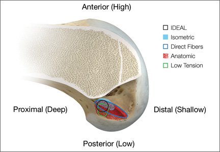
Alignment Analyses in the Varus Osteoarthritic Knee Using Computer Navigation
Osteoarthritic (OA) knees with varus deformities commonly present with tight, contracted medial collateral ligaments and soft-tissue sleeves.1 More severe varus deformities require more extensive medial releases on the concave side to optimize flexion-extension gaps. Excessive soft-tissue releases in milder varus deformities can result in medial instability in flexion and extension.2-4 Misjudgments in soft-tissue release can therefore lead to knee instability, an important cause of early total knee arthroplasty (TKA) failures.2,5,6 Some authors have reported difficulty in coronal plane balancing in knees with preoperative varus deformity of more than 20°.4,7
Surgeons often refer to varus as a description of coronal malalignment, mainly with the knee in extension. In the surgical setting, however, descriptions are given regarding differential medial soft-tissue tightness in extension and flexion. Balancing the knee in extension may not necessarily balance the knee in flexion. Thus, there is the concept of extension and flexion varus, which has not been well described in the literature. Releases on the anterior medial and posterior medial aspects of the proximal tibia have differential effects on flexion and extension gaps, respectively.2
Intraoperative alignment certainly has a pivotal role in component longevity.8 Since its advent in the 1990s, use of computer navigation in TKA has offered new hope for improving component alignment. Some authors routinely use computer navigation for intraoperative soft-tissue releases.9 A recent meta-analysis found that computer-navigated surgery is associated with fewer outliers in final component alignment compared with conventional TKA.10
Increased use of computer navigation in TKA at our institution in recent years has come with the observation that knees with severe extension varus seem to have correspondingly more severe flexion varus. Before computer navigation, coronal alignment of knees in flexion was almost impossible to measure because of the spatial alignment of the knees in that position.
We conducted a study to evaluate the relationship of extension and flexion varus in OA knees and to determine whether severity of fixed flexion deformity (FFD) in the sagittal plane correlates with severity of coronal plane varus deformity. We hypothesized that there would be differential varus in flexion and extension and that increasing knee extension varus would correlate closely with knee flexion varus beyond a certain tibiofemoral angle. We also hypothesized that severity of sagittal plane deformity will correlate with the severity of coronal plane deformity.
Patients and Methods
Data Collection
After this study was approved by our institution’s ethics review committee, we prospectively collected data from 403 consecutive computer-navigated TKAs performed at our institution between November 2008 and August 2011. Dr. Tan, who was not the primary physician, retrospectively analyzed the radiographic and navigation data.
Each patient’s knee varus-valgus angles were captured by Dr. Teo, an adult reconstruction surgeon, in standard fashion from maximal extension to 0º, 30º, 45º, 60º, 90º, and maximal flexion. An example of standard data capture appears in Table 1. With varus-hyperextension defined as –0.5° or less (more negative), neutral as 0°, and valgus-flexion as 0.5° or more, there were 362 varus knees, 41 valgus knees, and no neutral knees.
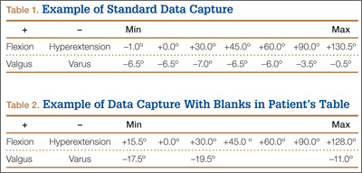
Study inclusion criteria were OA and varus deformity. Exclusion criteria were rheumatoid arthritis, other types of inflammatory arthritis, neuromuscular disorders, knees with valgus angulation, and incomplete data (Table 2). Figure 1 summarizes the inclusion/exclusion process, which left 317 knees available for study. Cases of incomplete data were likely due to computer errors or to inadvertent movement when navigation data were being acquired during surgery.
![]()
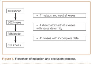
In conventional TKA, the main objective is to equalize flexion-extension gaps with knee at 90° flexion and 0° extension. The ability to achieve this often implies the knee will be balanced throughout its range of motion (ROM). From the data for the 317 study knees, 3 sets of values were extracted: varus angles from maximal knee extension (extension varus), varus angles from 90° knee flexion (flexion varus), and maximal knee extension. All knees were able to achieve 90° flexion.
Power Calculation
Our analysis used a correlation coefficient (r) of at least 0.5 at a 5% level of significance and power of 80%. With 317 knees, the study was more than adequately powered for significance.
Surgical and Navigation Technique
All patients underwent either general or regional anesthesia for their surgeries, which were performed by Dr. Teo. Standard medial parapatellar arthrotomy was performed. Navigation pins were then inserted into the femur and tibia outside the knee wound. Anatomical reference points were digitized per routine navigation requirements. (The reference for varus-valgus alignment of the femur is the mechanical femur axis defined by the digitized hip center and knee center, and the reference for varus-valgus alignment of the tibia is the mechanical tibia axis defined by the digitized tibia center and calculated ankle center. The ankle center is calculated by dividing the digitized transmalleolar axis according to a ratio of 56% lateral to 44% medial with the inherent navigation software.) Our institution uses an imageless navigation system (Navigation System II; Stryker Orthopedics, Mahwah, New Jersey).
The leg was then brought from maximal knee extension to maximal knee flexion to assess preoperative ROM, which indicates inherent flexion contracture or hyperextension. Varus-valgus measurements of the knee were then generated as part of the navigation software protocol. These measurements were obtained without additional varus or valgus stress applied to the knee and before any bony resection. The rest of the operation was completed using navigation to guide bony resection and soft-tissue balancing. The final components used were all cemented cruciate-substituting TKA implants. After component insertion, the knee was again brought through ROM from maximal knee extension to maximal knee flexion to assess postoperative ROM before wound closure.
Extension and Flexion Varus
As none of the patients in the flexion varus dataset (range, –0.5° to –19°) had a varus deformity of more than 20° at 90° flexion, we used a cutoff of 10° to divide these patients into 2 subgroups: less than 10° (237 knees) and 10° or more (80 knees). The extension varus dataset ranged from –0.5° to –24°. Incremental values of –0.5° to –24° in this dataset were then analyzed against the 90° flexion varus subgroups using logistic regression. A scatterplot of the relationship between extension and flexion varus is shown in Figure 2. The probability function was then derived and a probability graph plotted.
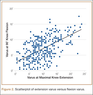
FFD and Extension and Flexion Varus
Maximal knee extension, obtained from intraoperative navigation measurements, ranged from –9° (hyperextension) to 33° (FFD) and maximal knee flexion ranged from 90° to 146°. Ninety-two knees had slight hyperextension, and 6 were neutral. Of the 317 OA knees with varus deformity, 219 (69%) had FFD. This sagittal plane alignment parameter was analyzed against coronal plane alignment in maximal knee extension and 90° knee flexion to determine if increasing severity of FFD corresponds with increasing extension or flexion varus.
Statistical Analysis
Statistical analysis was performed with Stata 10.1 (Statacorp, College Station, Texas). Significance was set at P < .05.
Results
Extension and Flexion Varus
Patient demographic data are listed in Table 3. Univariate logistic regression analysis revealed that age (P = .110), body mass index (P = .696), and sex (P = .584) did not affect the association between preoperative extension and flexion varus.
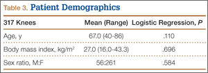
Mean (SD) preoperative extension varus was –9.9° (4.80°), and mean (SD) preoperative flexion 90° varus was –7.02° (3.74°). Linear regression of the data showed a significant positive correlation between preoperative extension varus and flexion varus (Pearson correlation coefficient, 0.57; P < .0001). The probability function was determined as follows: Probability of having flexion varus of more than 10° = 1 / (1 + e–z), where z = –4.014 – 0.265 × extension varus. Plotting the probability graph of flexion varus against varus angles at maximal knee extension from the probability formula yielded a sigmoid graph (Figure 3). The most linear part of the graph corresponds to the 10° to 20° of extension varus (solid line), demonstrating an almost linear increase in the probability of having more than 10° flexion varus with increasing extension varus from 10° to 20°. For extension varus of 20° or more, the probability of having flexion varus of more than 10° approaches 1.
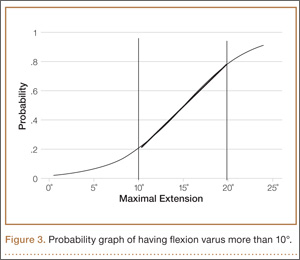
FFD and Extension and Flexion Varus
Mean (SD) preoperative maximal knee extension (analogous to FFD) was 4.41° (7.50°), mean (SD) extension varus was –9.9° (4.80°), and mean (SD) 90° flexion varus was –7.02° (3.74°). We did not find any correlation between preoperative FFD and preoperative flexion varus (r = –0.02; P = .6583) or extension varus (r = –0.11; P = .046) (Figure 4).
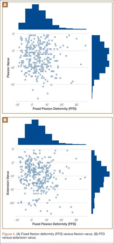
Postoperative Alignment
Of the 317 OA knees, 18 had incomplete navigation-acquired postoperative alignment data. The postoperative alignment of the other 299 knees at various degrees of knee flexion is illustrated with a box-and-whisker plot (Figure 5).
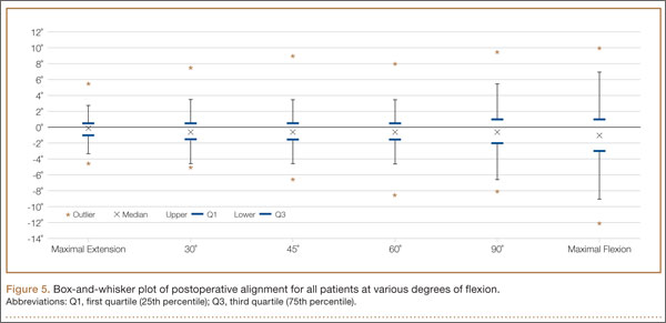
Knees With Severe Extension Varus
Fourteen of the 15 knees with severe extension varus (>20°) had flexion varus of more than 9° (range, –9° to –17.5°, with only 1 outlier, at –5°). For the 15 patients, maximal knee extension ranged from –9° hyperextension to 27.5° FFD. Six knees had slight hyperextension, and 9 had FFD demonstrating large variability in sagittal alignment. Despite severe preoperative coronal deformity, all 15 knees had satisfactory deformity correction. Preoperative and postoperative knee alignment data for these 15 knees appear in Table 4 and Figure 6, respectively.
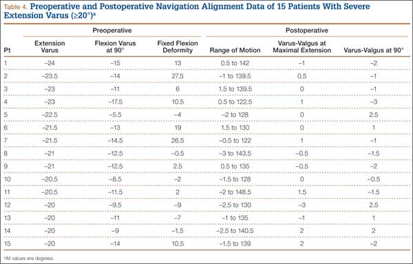
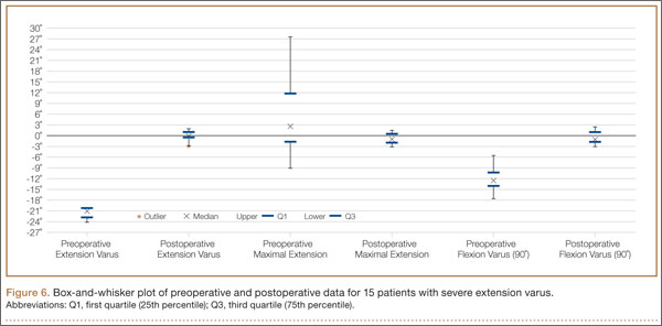
Discussion
OA varus knees represent a majority of the cases being managed by orthopedic surgeons. Soft-tissue contractures involving the medial collateral ligament (MCL), posteromedial capsule, pes anserinus, and semimembranosus muscle are commonly encountered. Bone loss may also occur on the tibial and femoral joint surfaces in knees with severe angular deformity. In an OA varus knee, bone loss tends to be mainly on the medial tibial plateau and usually on the posterior aspect of the tibia because flexion contractures often are concomitant with these marked deformities.11 Therefore, a varus deformity is apparent whether the knee is extended or flexed. Our results showed a correlation between extension and flexion varus in OA varus knees. In contrast, for a valgus deformity, as bone loss can occur on both the tibial and femoral surfaces,11 a similar correlation may not be seen. For that reason, and because there were only 41 valgus knees in this study, they were excluded. For FFD, soft-tissue contractures often involve both the posterior capsule and the posterior cruciate ligament (PCL). Posterior osteophytes often cause tenting of the posterior capsule in knees with FFD. Anteriorly, growth of osteophytes at the tibial spine and intercondylar notch of the femur can result in bony causes of restricted knee extension.12
One would expect increased coronal plane angular deformity to correspond to more severe FFD in the sagittal plane because the same pathology affects soft tissue or bones in an OA knee in both planes. Interestingly, our study results proved otherwise. FFD did not correlate with degree of extension or flexion varus severity. This phenomenon has not been described in the literature likely because clinical measurements of flexion varus and FFD were difficult to perform because of the spatial alignment of the knee in flexion. In recent years, however, computer navigation technology has made such measurements possible.
Mihalko and colleagues2 established that soft-tissue releases on different parts of the proximal tibia have different effects on soft-tissue balancing in flexion and extension. In knees with extension varus, more releases are required on the posterior medial aspect of the tibia (the posterior oblique fibers of the superficial MCL, the posteromedial capsule, and, sometimes, the semimembranosus), whereas knees with flexion varus require more releases on the anterior medial aspect of the tibia (the deep MCL, the anterior fibers of the superficial MCL, and, sometimes, the pes anserinus attachment).13 Consequently, soft-tissue stabilizers seem to have different functions in flexion and extension and cannot reliably be released solely in extension or flexion for optimal gap balancing during TKA.2 Other authors, in cadaveric studies, have found that a larger amount of coronal deformity correction is achieved with more distal soft-tissue releases from the joint line.9,14 Surgical techniques for correcting FFD include removal of prominent anterior and posterior osteophytes, posterior capsular releases, sometimes PCL sacrifices, and even gastrocnemius recession.12
In our study, all 14 patients with severe extension and correspondingly severe flexion varus needed not only modest posterior medial soft-tissue releases for the severe extension varus, but also modest anterior medial releases for the flexion varus. The respective soft-tissue releases were confirmed in real time with computer navigation sequentially after bony resection and osteophyte removal. With this method, we restored final postoperative alignment to within 3° of the mechanical axis (Figure 6). Our experience here led us to believe that, with these patients, modest anterior medial and posterior medial releases could be performed at the start of surgery, as severe extension varus (>20°) almost certainly equates to severe flexion varus (>10°). Therein lies the clinical relevance of our study. However, not all patients with severe coronal plane deformity have correspondingly severe sagittal plane deformity in the form of FFD, as illustrated in our study. Therefore, not all patients with severe varus knee deformity need aggressive posterior capsular release or PCL recession to correct FFD. Some patients have mild hyperextension, which can be attributed partly to the postanesthesia effects of soft-tissue laxity. It is unclear exactly how much anesthesia contributes to this difference in sagittal alignment, though the majority of our patients had FFD. It is not our intent here to discuss the surgical techniques of soft-tissue balancing or to advocate routine use of computer navigation.
Many factors (eg, medial femoral condyle bone loss, medial tibial plateau bone loss, femur or tibia bowing, medial soft-tissue contracture) can contribute to varus malalignment. Current navigation technology cannot isolate the causes of varus alignment, and we did not intend to investigate them in this study. Our primary aim was to assess for a correlation between overall extension varus alignment and expected flexion varus. We also wanted to analyze the correlation between FFD and the coronal plane alignment, in extension and flexion, contributed by the combined bony and soft-tissue components in OA varus knees.
The strengths of this study are that it was a single-surgeon series with knee data from consecutive patients who had computer-navigated TKA. Patient data were prospectively generated from the navigation software and retrospectively analyzed. All navigation alignment was performed by a single surgeon, thereby eliminating examination bias during the time knee alignment data were being obtained. The study was adequately powered and had a large number of patients for data analysis. The authors believe that this is the first study to analyze alignment in both the coronal and sagittal plane in varus OA knees.
We acknowledge a few limitations in our study. Although several investigators have found that navigation can be used to achieve accurate postoperative alignment,10,15,16 subtle errors may be inadvertently introduced at different points of alignment measurement. These error points include identification of visually selected anatomical landmarks; kinematic registration of hip, knee, and ankle; and intraoperative changes in the navigation environment (eg, inadvertent movement of pins or rigid bodies). In addition, different surgeons have different techniques for kinematic registration. However, the surgeries in our study were performed by the same surgeon, so this confounding factor was effectively removed. Another limitation was that navigation alignment was obtained during surgery, when patients were under anesthesia and in a supine, non-weight-bearing position, whereas routine clinical weight-bearing radiographs are taken with nonanesthetized patients and this might overestimate the deformities intraoperatively. However, all parameters were measured in the same patient under the same anesthetic effects, so this should not have affected the analyses. Most surgeons would make an intraoperative assessment of the severity of any deformity before the surgery proper anyway. Nevertheless, some authors have found that knee alignment obtained with intraoperative navigation correlated well with alignment obtained with weight-bearing radiographs.17,18
Conclusion
Our study results showed that, in OA varus knees, extension varus highly correlated with flexion varus. However, there was no correlation between FFD and coronal plane varus deformity.
1. Engh GA. The difficult knee: severe varus and valgus. Clin Orthop. 2003;(416):58-63.
2. Mihalko WM, Saleh KJ, Krackow KA, Whiteside LA. Soft-tissue balancing during total knee arthroplasty in the varus knee. J Am Acad Orthop Surg. 2009;17(12):766-774.
3. Ranawat CS, Flynn WF Jr, Saddler S, Hansraj KK, Maynard MJ. Long-term results of the total condylar knee arthroplasty. A 15-year survivorship study. Clin Orthop. 1993;(286):94-102.
4. Ritter MA, Faris GW, Faris PM, Davis KE. Total knee arthroplasty in patients with angular varus or valgus deformities of > or = 20 degrees. J Arthroplasty. 2004;19(7):862-866.
5. Parratte S, Pagnano MW. Instability after total knee arthroplasty. J Bone Joint Surg Am. 2008;90(1):184-194.
6. Sharkey PF, Hozack WJ, Rothman RH, Shastri S, Jacoby SM. Insall Award paper. Why are total knee arthroplasties failing today? Clin Orthop. 2002;(404):7-13.
7. Mullaji AB, Padmanabhan V, Jindal G. Total knee arthroplasty for profound varus deformity: technique and radiological results in 173 knees with varus of more than 20 degrees. J Arthroplasty. 2005;20(5):550-561.
8. Jeffery RS, Morris RW, Denham RA. Coronal alignment after total knee replacement. J Bone Joint Surg Br. 1991;73(5):709-714.
9. Luring C, Hüfner T, Perlick L, Bäthis H, Krettek C, Grifka J. The effectiveness of sequential medial soft tissue release on coronal alignment in total knee arthroplasty: using a computer navigation model. J Arthroplasty. 2006;21(3):428-434.
10. Hetaimish BM, Khan MM, Simunovic N, Al-Harbi HH, Bhandari M, Zalzal PK. Meta-analysis of navigation vs conventional total knee arthroplasty. J Arthroplasty. 2012;27(6):1177-1182.
11. Insall JN, Easley ME. Surgical techniques and instrumentation in total knee arthroplasty. In: Insall JN, Scott WN, eds. Surgery of the Knee. Vol 2. 3rd ed. New York, NY: Churchill Livingstone; 2001:1553-1620.
12. Scuderi GR, Tria AJ, eds. Surgical Techniques in Total Knee Arthroplasty. New York, NY: Springer-Verlag; 2002.
13. Whiteside LA, Saeki K, Mihalko WM. Functional medial ligament balancing in total knee arthroplasty. Clin Orthop. 2000;(380):45-57.
14. Matsueda M, Gengerke TR, Murphy M, Lew WD, Gustilo RB. Soft tissue release in total knee arthroplasty. Cadaver study using knees without deformities. Clin Orthop. 1999;(366):264-273.
15. Haaker RG, Stockheim M, Kamp M, Proff G, Breitenfelder J, Ottersbach A. Computer-assisted navigation increases precision of component placement in total knee arthroplasty. Clin Orthop. 2005;(433):152-159.
16. Mullaji AB, Kanna R, Marawar S, Kohli A, Sharma A. Comparison of limb and component alignment using computer-assisted navigation versus image intensifier–guided conventional total knee arthroplasty: a prospective, randomized, single-surgeon study of 467 knees. J Arthroplasty. 2007;22(7):953-959.
17. Colebatch AN, Hart DJ, Zhai G, Williams FM, Spector TD, Arden NK. Effective measurement of knee alignment using AP knee radiographs. Knee. 2009;16(1):42-45.
18. Yaffe MA, Koo SS, Stulberg SD. Radiographic and navigation measurements of TKA limb alignment do not correlate. Clin Orthop. 2008;466(11):2736-2744.
Osteoarthritic (OA) knees with varus deformities commonly present with tight, contracted medial collateral ligaments and soft-tissue sleeves.1 More severe varus deformities require more extensive medial releases on the concave side to optimize flexion-extension gaps. Excessive soft-tissue releases in milder varus deformities can result in medial instability in flexion and extension.2-4 Misjudgments in soft-tissue release can therefore lead to knee instability, an important cause of early total knee arthroplasty (TKA) failures.2,5,6 Some authors have reported difficulty in coronal plane balancing in knees with preoperative varus deformity of more than 20°.4,7
Surgeons often refer to varus as a description of coronal malalignment, mainly with the knee in extension. In the surgical setting, however, descriptions are given regarding differential medial soft-tissue tightness in extension and flexion. Balancing the knee in extension may not necessarily balance the knee in flexion. Thus, there is the concept of extension and flexion varus, which has not been well described in the literature. Releases on the anterior medial and posterior medial aspects of the proximal tibia have differential effects on flexion and extension gaps, respectively.2
Intraoperative alignment certainly has a pivotal role in component longevity.8 Since its advent in the 1990s, use of computer navigation in TKA has offered new hope for improving component alignment. Some authors routinely use computer navigation for intraoperative soft-tissue releases.9 A recent meta-analysis found that computer-navigated surgery is associated with fewer outliers in final component alignment compared with conventional TKA.10
Increased use of computer navigation in TKA at our institution in recent years has come with the observation that knees with severe extension varus seem to have correspondingly more severe flexion varus. Before computer navigation, coronal alignment of knees in flexion was almost impossible to measure because of the spatial alignment of the knees in that position.
We conducted a study to evaluate the relationship of extension and flexion varus in OA knees and to determine whether severity of fixed flexion deformity (FFD) in the sagittal plane correlates with severity of coronal plane varus deformity. We hypothesized that there would be differential varus in flexion and extension and that increasing knee extension varus would correlate closely with knee flexion varus beyond a certain tibiofemoral angle. We also hypothesized that severity of sagittal plane deformity will correlate with the severity of coronal plane deformity.
Patients and Methods
Data Collection
After this study was approved by our institution’s ethics review committee, we prospectively collected data from 403 consecutive computer-navigated TKAs performed at our institution between November 2008 and August 2011. Dr. Tan, who was not the primary physician, retrospectively analyzed the radiographic and navigation data.
Each patient’s knee varus-valgus angles were captured by Dr. Teo, an adult reconstruction surgeon, in standard fashion from maximal extension to 0º, 30º, 45º, 60º, 90º, and maximal flexion. An example of standard data capture appears in Table 1. With varus-hyperextension defined as –0.5° or less (more negative), neutral as 0°, and valgus-flexion as 0.5° or more, there were 362 varus knees, 41 valgus knees, and no neutral knees.
Study inclusion criteria were OA and varus deformity. Exclusion criteria were rheumatoid arthritis, other types of inflammatory arthritis, neuromuscular disorders, knees with valgus angulation, and incomplete data (Table 2). Figure 1 summarizes the inclusion/exclusion process, which left 317 knees available for study. Cases of incomplete data were likely due to computer errors or to inadvertent movement when navigation data were being acquired during surgery.
![]()
In conventional TKA, the main objective is to equalize flexion-extension gaps with knee at 90° flexion and 0° extension. The ability to achieve this often implies the knee will be balanced throughout its range of motion (ROM). From the data for the 317 study knees, 3 sets of values were extracted: varus angles from maximal knee extension (extension varus), varus angles from 90° knee flexion (flexion varus), and maximal knee extension. All knees were able to achieve 90° flexion.
Power Calculation
Our analysis used a correlation coefficient (r) of at least 0.5 at a 5% level of significance and power of 80%. With 317 knees, the study was more than adequately powered for significance.
Surgical and Navigation Technique
All patients underwent either general or regional anesthesia for their surgeries, which were performed by Dr. Teo. Standard medial parapatellar arthrotomy was performed. Navigation pins were then inserted into the femur and tibia outside the knee wound. Anatomical reference points were digitized per routine navigation requirements. (The reference for varus-valgus alignment of the femur is the mechanical femur axis defined by the digitized hip center and knee center, and the reference for varus-valgus alignment of the tibia is the mechanical tibia axis defined by the digitized tibia center and calculated ankle center. The ankle center is calculated by dividing the digitized transmalleolar axis according to a ratio of 56% lateral to 44% medial with the inherent navigation software.) Our institution uses an imageless navigation system (Navigation System II; Stryker Orthopedics, Mahwah, New Jersey).
The leg was then brought from maximal knee extension to maximal knee flexion to assess preoperative ROM, which indicates inherent flexion contracture or hyperextension. Varus-valgus measurements of the knee were then generated as part of the navigation software protocol. These measurements were obtained without additional varus or valgus stress applied to the knee and before any bony resection. The rest of the operation was completed using navigation to guide bony resection and soft-tissue balancing. The final components used were all cemented cruciate-substituting TKA implants. After component insertion, the knee was again brought through ROM from maximal knee extension to maximal knee flexion to assess postoperative ROM before wound closure.
Extension and Flexion Varus
As none of the patients in the flexion varus dataset (range, –0.5° to –19°) had a varus deformity of more than 20° at 90° flexion, we used a cutoff of 10° to divide these patients into 2 subgroups: less than 10° (237 knees) and 10° or more (80 knees). The extension varus dataset ranged from –0.5° to –24°. Incremental values of –0.5° to –24° in this dataset were then analyzed against the 90° flexion varus subgroups using logistic regression. A scatterplot of the relationship between extension and flexion varus is shown in Figure 2. The probability function was then derived and a probability graph plotted.
FFD and Extension and Flexion Varus
Maximal knee extension, obtained from intraoperative navigation measurements, ranged from –9° (hyperextension) to 33° (FFD) and maximal knee flexion ranged from 90° to 146°. Ninety-two knees had slight hyperextension, and 6 were neutral. Of the 317 OA knees with varus deformity, 219 (69%) had FFD. This sagittal plane alignment parameter was analyzed against coronal plane alignment in maximal knee extension and 90° knee flexion to determine if increasing severity of FFD corresponds with increasing extension or flexion varus.
Statistical Analysis
Statistical analysis was performed with Stata 10.1 (Statacorp, College Station, Texas). Significance was set at P < .05.
Results
Extension and Flexion Varus
Patient demographic data are listed in Table 3. Univariate logistic regression analysis revealed that age (P = .110), body mass index (P = .696), and sex (P = .584) did not affect the association between preoperative extension and flexion varus.
Mean (SD) preoperative extension varus was –9.9° (4.80°), and mean (SD) preoperative flexion 90° varus was –7.02° (3.74°). Linear regression of the data showed a significant positive correlation between preoperative extension varus and flexion varus (Pearson correlation coefficient, 0.57; P < .0001). The probability function was determined as follows: Probability of having flexion varus of more than 10° = 1 / (1 + e–z), where z = –4.014 – 0.265 × extension varus. Plotting the probability graph of flexion varus against varus angles at maximal knee extension from the probability formula yielded a sigmoid graph (Figure 3). The most linear part of the graph corresponds to the 10° to 20° of extension varus (solid line), demonstrating an almost linear increase in the probability of having more than 10° flexion varus with increasing extension varus from 10° to 20°. For extension varus of 20° or more, the probability of having flexion varus of more than 10° approaches 1.
FFD and Extension and Flexion Varus
Mean (SD) preoperative maximal knee extension (analogous to FFD) was 4.41° (7.50°), mean (SD) extension varus was –9.9° (4.80°), and mean (SD) 90° flexion varus was –7.02° (3.74°). We did not find any correlation between preoperative FFD and preoperative flexion varus (r = –0.02; P = .6583) or extension varus (r = –0.11; P = .046) (Figure 4).
Postoperative Alignment
Of the 317 OA knees, 18 had incomplete navigation-acquired postoperative alignment data. The postoperative alignment of the other 299 knees at various degrees of knee flexion is illustrated with a box-and-whisker plot (Figure 5).
Knees With Severe Extension Varus
Fourteen of the 15 knees with severe extension varus (>20°) had flexion varus of more than 9° (range, –9° to –17.5°, with only 1 outlier, at –5°). For the 15 patients, maximal knee extension ranged from –9° hyperextension to 27.5° FFD. Six knees had slight hyperextension, and 9 had FFD demonstrating large variability in sagittal alignment. Despite severe preoperative coronal deformity, all 15 knees had satisfactory deformity correction. Preoperative and postoperative knee alignment data for these 15 knees appear in Table 4 and Figure 6, respectively.
Discussion
OA varus knees represent a majority of the cases being managed by orthopedic surgeons. Soft-tissue contractures involving the medial collateral ligament (MCL), posteromedial capsule, pes anserinus, and semimembranosus muscle are commonly encountered. Bone loss may also occur on the tibial and femoral joint surfaces in knees with severe angular deformity. In an OA varus knee, bone loss tends to be mainly on the medial tibial plateau and usually on the posterior aspect of the tibia because flexion contractures often are concomitant with these marked deformities.11 Therefore, a varus deformity is apparent whether the knee is extended or flexed. Our results showed a correlation between extension and flexion varus in OA varus knees. In contrast, for a valgus deformity, as bone loss can occur on both the tibial and femoral surfaces,11 a similar correlation may not be seen. For that reason, and because there were only 41 valgus knees in this study, they were excluded. For FFD, soft-tissue contractures often involve both the posterior capsule and the posterior cruciate ligament (PCL). Posterior osteophytes often cause tenting of the posterior capsule in knees with FFD. Anteriorly, growth of osteophytes at the tibial spine and intercondylar notch of the femur can result in bony causes of restricted knee extension.12
One would expect increased coronal plane angular deformity to correspond to more severe FFD in the sagittal plane because the same pathology affects soft tissue or bones in an OA knee in both planes. Interestingly, our study results proved otherwise. FFD did not correlate with degree of extension or flexion varus severity. This phenomenon has not been described in the literature likely because clinical measurements of flexion varus and FFD were difficult to perform because of the spatial alignment of the knee in flexion. In recent years, however, computer navigation technology has made such measurements possible.
Mihalko and colleagues2 established that soft-tissue releases on different parts of the proximal tibia have different effects on soft-tissue balancing in flexion and extension. In knees with extension varus, more releases are required on the posterior medial aspect of the tibia (the posterior oblique fibers of the superficial MCL, the posteromedial capsule, and, sometimes, the semimembranosus), whereas knees with flexion varus require more releases on the anterior medial aspect of the tibia (the deep MCL, the anterior fibers of the superficial MCL, and, sometimes, the pes anserinus attachment).13 Consequently, soft-tissue stabilizers seem to have different functions in flexion and extension and cannot reliably be released solely in extension or flexion for optimal gap balancing during TKA.2 Other authors, in cadaveric studies, have found that a larger amount of coronal deformity correction is achieved with more distal soft-tissue releases from the joint line.9,14 Surgical techniques for correcting FFD include removal of prominent anterior and posterior osteophytes, posterior capsular releases, sometimes PCL sacrifices, and even gastrocnemius recession.12
In our study, all 14 patients with severe extension and correspondingly severe flexion varus needed not only modest posterior medial soft-tissue releases for the severe extension varus, but also modest anterior medial releases for the flexion varus. The respective soft-tissue releases were confirmed in real time with computer navigation sequentially after bony resection and osteophyte removal. With this method, we restored final postoperative alignment to within 3° of the mechanical axis (Figure 6). Our experience here led us to believe that, with these patients, modest anterior medial and posterior medial releases could be performed at the start of surgery, as severe extension varus (>20°) almost certainly equates to severe flexion varus (>10°). Therein lies the clinical relevance of our study. However, not all patients with severe coronal plane deformity have correspondingly severe sagittal plane deformity in the form of FFD, as illustrated in our study. Therefore, not all patients with severe varus knee deformity need aggressive posterior capsular release or PCL recession to correct FFD. Some patients have mild hyperextension, which can be attributed partly to the postanesthesia effects of soft-tissue laxity. It is unclear exactly how much anesthesia contributes to this difference in sagittal alignment, though the majority of our patients had FFD. It is not our intent here to discuss the surgical techniques of soft-tissue balancing or to advocate routine use of computer navigation.
Many factors (eg, medial femoral condyle bone loss, medial tibial plateau bone loss, femur or tibia bowing, medial soft-tissue contracture) can contribute to varus malalignment. Current navigation technology cannot isolate the causes of varus alignment, and we did not intend to investigate them in this study. Our primary aim was to assess for a correlation between overall extension varus alignment and expected flexion varus. We also wanted to analyze the correlation between FFD and the coronal plane alignment, in extension and flexion, contributed by the combined bony and soft-tissue components in OA varus knees.
The strengths of this study are that it was a single-surgeon series with knee data from consecutive patients who had computer-navigated TKA. Patient data were prospectively generated from the navigation software and retrospectively analyzed. All navigation alignment was performed by a single surgeon, thereby eliminating examination bias during the time knee alignment data were being obtained. The study was adequately powered and had a large number of patients for data analysis. The authors believe that this is the first study to analyze alignment in both the coronal and sagittal plane in varus OA knees.
We acknowledge a few limitations in our study. Although several investigators have found that navigation can be used to achieve accurate postoperative alignment,10,15,16 subtle errors may be inadvertently introduced at different points of alignment measurement. These error points include identification of visually selected anatomical landmarks; kinematic registration of hip, knee, and ankle; and intraoperative changes in the navigation environment (eg, inadvertent movement of pins or rigid bodies). In addition, different surgeons have different techniques for kinematic registration. However, the surgeries in our study were performed by the same surgeon, so this confounding factor was effectively removed. Another limitation was that navigation alignment was obtained during surgery, when patients were under anesthesia and in a supine, non-weight-bearing position, whereas routine clinical weight-bearing radiographs are taken with nonanesthetized patients and this might overestimate the deformities intraoperatively. However, all parameters were measured in the same patient under the same anesthetic effects, so this should not have affected the analyses. Most surgeons would make an intraoperative assessment of the severity of any deformity before the surgery proper anyway. Nevertheless, some authors have found that knee alignment obtained with intraoperative navigation correlated well with alignment obtained with weight-bearing radiographs.17,18
Conclusion
Our study results showed that, in OA varus knees, extension varus highly correlated with flexion varus. However, there was no correlation between FFD and coronal plane varus deformity.
1. Engh GA. The difficult knee: severe varus and valgus. Clin Orthop. 2003;(416):58-63.
2. Mihalko WM, Saleh KJ, Krackow KA, Whiteside LA. Soft-tissue balancing during total knee arthroplasty in the varus knee. J Am Acad Orthop Surg. 2009;17(12):766-774.
3. Ranawat CS, Flynn WF Jr, Saddler S, Hansraj KK, Maynard MJ. Long-term results of the total condylar knee arthroplasty. A 15-year survivorship study. Clin Orthop. 1993;(286):94-102.
4. Ritter MA, Faris GW, Faris PM, Davis KE. Total knee arthroplasty in patients with angular varus or valgus deformities of > or = 20 degrees. J Arthroplasty. 2004;19(7):862-866.
5. Parratte S, Pagnano MW. Instability after total knee arthroplasty. J Bone Joint Surg Am. 2008;90(1):184-194.
6. Sharkey PF, Hozack WJ, Rothman RH, Shastri S, Jacoby SM. Insall Award paper. Why are total knee arthroplasties failing today? Clin Orthop. 2002;(404):7-13.
7. Mullaji AB, Padmanabhan V, Jindal G. Total knee arthroplasty for profound varus deformity: technique and radiological results in 173 knees with varus of more than 20 degrees. J Arthroplasty. 2005;20(5):550-561.
8. Jeffery RS, Morris RW, Denham RA. Coronal alignment after total knee replacement. J Bone Joint Surg Br. 1991;73(5):709-714.
9. Luring C, Hüfner T, Perlick L, Bäthis H, Krettek C, Grifka J. The effectiveness of sequential medial soft tissue release on coronal alignment in total knee arthroplasty: using a computer navigation model. J Arthroplasty. 2006;21(3):428-434.
10. Hetaimish BM, Khan MM, Simunovic N, Al-Harbi HH, Bhandari M, Zalzal PK. Meta-analysis of navigation vs conventional total knee arthroplasty. J Arthroplasty. 2012;27(6):1177-1182.
11. Insall JN, Easley ME. Surgical techniques and instrumentation in total knee arthroplasty. In: Insall JN, Scott WN, eds. Surgery of the Knee. Vol 2. 3rd ed. New York, NY: Churchill Livingstone; 2001:1553-1620.
12. Scuderi GR, Tria AJ, eds. Surgical Techniques in Total Knee Arthroplasty. New York, NY: Springer-Verlag; 2002.
13. Whiteside LA, Saeki K, Mihalko WM. Functional medial ligament balancing in total knee arthroplasty. Clin Orthop. 2000;(380):45-57.
14. Matsueda M, Gengerke TR, Murphy M, Lew WD, Gustilo RB. Soft tissue release in total knee arthroplasty. Cadaver study using knees without deformities. Clin Orthop. 1999;(366):264-273.
15. Haaker RG, Stockheim M, Kamp M, Proff G, Breitenfelder J, Ottersbach A. Computer-assisted navigation increases precision of component placement in total knee arthroplasty. Clin Orthop. 2005;(433):152-159.
16. Mullaji AB, Kanna R, Marawar S, Kohli A, Sharma A. Comparison of limb and component alignment using computer-assisted navigation versus image intensifier–guided conventional total knee arthroplasty: a prospective, randomized, single-surgeon study of 467 knees. J Arthroplasty. 2007;22(7):953-959.
17. Colebatch AN, Hart DJ, Zhai G, Williams FM, Spector TD, Arden NK. Effective measurement of knee alignment using AP knee radiographs. Knee. 2009;16(1):42-45.
18. Yaffe MA, Koo SS, Stulberg SD. Radiographic and navigation measurements of TKA limb alignment do not correlate. Clin Orthop. 2008;466(11):2736-2744.
Targeting a New Safe Zone: A Step in the Development of Patient-Specific Component Positioning for Total Hip Arthroplasty
Postoperative dislocation remains a common complication of primary total hip arthroplasties (THAs), affecting less than 1% to more than 10% in reported series.1,2 In large datasets for modern implants, the incidence of dislocation is 2% to 4%.3,4 Given that more than 200,000 THAs are performed in the United States each year,5 these low percentages represent a large number of patients. The multiplex patient variables that affect THA stability include age, sex, body mass index (BMI), and comorbid conditions.6-8 Surgical approach, restoration of leg length and femoral offset, femoral head size, and component positioning are also important surgical factors that can increase or decrease the incidence of dislocation.3,8,9 In particular, appropriate acetabular component orientation is crucial; surgeons can control this factor and thereby limit the occurrence of dislocation.10 Furthermore, acetabular malpositioning can increase the risk of liner fractures and accelerate bearing-surface wear.11-14
To minimize the risk of postoperative dislocation, surgeons traditionally have targeted the Lewinnek safe zone, with its mean (SD) inclination of 40° (10°) and mean (SD) anteversion of 15° (10°), for acetabular component orientation.15 However, the applicability of this target zone to preventing hip instability using modern implant designs, components, and surgical techniques remains unknown. Achieving acetabular orientation based on maximizing range of motion (ROM) before impingement may be optimal, with anteversion from 20° to 30° and inclination from 40° to 45°.16,17 Furthermore, mean (SD) native acetabular anteversion ranges from 21.3° (6.2°) for men to 24.6° (6.6°) for women.18 Placing THA acetabular components near the native range for anteversion may best provide impingement-free ROM and thus optimize THA stability,16,19 but this has not been proved in a clinical study.
Early dislocation is typically classified as occurring within 6 months after surgery,9 with almost 80% of dislocations occurring within 3 months after surgery.10 Surgeon-specific factors, such as acetabular component positioning, are thought to have a predominant effect on dislocations in the early postoperative period.10 Computer-assisted surgery (CAS), such as imageless navigation, is more accurate than conventional methods for acetabular component placement,20-23 but the clinical relevance of improving accuracy for acetabular component placement has not been shown with respect to altering patient outcomes.23
We conducted a study in a large single-surgeon patient cohort to determine the incidence of early postoperative dislocation with target anteversion increased to 25°, approximating mean native acetabular anteversion.16,19 In addition, we sought to determine the accuracy of imageless navigation in achieving target acetabular component placement.
Materials and Methods
After obtaining institutional review board approval for this retrospective clinical study, we reviewed 671 consecutive cases of primary THA performed by a single surgeon using an imageless CAS system (AchieveCAS; Smith & Nephew, Memphis, Tennessee) between July 2006 and October 2012. THAs were excluded if a metal-on-metal bearing surface was used, if an adequate 6-week postoperative supine anteroposterior (AP) pelvis radiograph was unavailable, or if 6-month clinical follow-up findings were not available (Figure 1). The quality of AP radiographs was deemed poor if they were not centered on the symphysis pubis and if the sacrococcygeal joint was not centered over the symphysis pubis. After exclusion criteria were applied, 553 arthroplasties (479 patients) with a mean (SD) follow-up of 2.4 (1.4) years remained. Perioperative demographic data and component sizes are listed in Table 1.
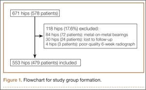
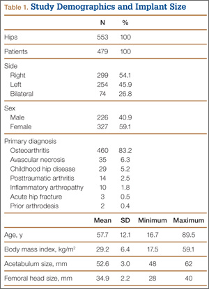
During surgery, the anterior pelvic plane, defined by the anterior-superior iliac spines and pubic tubercle, was registered with the CAS system with the patient in the supine position. THA was performed with the patient in the lateral decubitus position using a posterolateral technique. For all patients, the surgeon used a hemispherical acetabular component (R3 Acetabular System; Smith & Nephew); bearings that were either metal on highly cross-linked polyethylene (XLPE) or Oxinium (Smith & Nephew) on XLPE; and neutral XLPE acetabular inserts. The goals for acetabular inclination and anteversion were 40° and 25°, respectively, with ±10° each for the target zone. The CAS system was used to adjust target anteversion for sagittal pelvic tilt.24 Uncemented femoral components were used for all patients, and the goal for femoral component anteversion was 15°. Transosseous repair of the posterior capsule and short external rotators was performed after component implantation.25
On each 6-week postoperative radiograph, acetabular orientation was measured with Ein-Bild-Röntgen-Analyse (EBRA; University of Innsbruck, Austria) software, which provides a validated method for measuring acetabular inclination and anteversion on supine AP pelvis radiographs.10,26 Pelvic boundaries were delineated with grid lines defining pelvic position. Reference points around the projections of the prosthetic femoral head, the hemispherical cup, and the rim of the cup were marked (Figure 2). EBRA calculated radiographic inclination and anteversion of the acetabular component based on the spatial position of the cup center in relation to the plane of the radiograph and the pelvic position.26
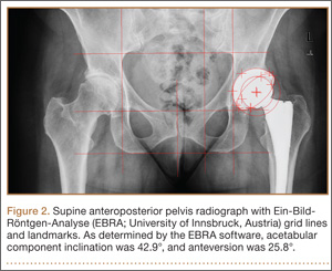
Charts were reviewed to identify patients with early postoperative dislocations, as well as dislocation timing, recurrence, and other characteristics. We defined early dislocation as instability occurring within 6 months after surgery. Revision surgery for instability was also identified.
For the statistical analysis, orientation error was defined as the absolute value of the difference between target orientation (40° inclination, 25° anteversion) and radiographic measurements. Repeated-measures multiple regression with the generalized estimating equations approach was used to identify baseline patient characteristics (age, sex, BMI, primary diagnosis, laterality) associated with component positioning outside of our targeted ranges for inclination and anteversion. Fisher exact tests were used to examine the relationship between dislocation and component placement in either the Lewinnek safe zone or our targeted zone. All tests were 2-sided with a significance level of .05. All analyses were performed with SAS for Windows 9.3 (SAS Institute, Cary, North Carolina).
Results
Mean (SD) acetabular inclination was 42.2° (4.9°) (range, 27.6°-65.0°), with a mean (SD) orientation error of 4.2° (3.4°) (Figure 3A). Mean (SD) anteversion was 23.9° (6.5°) (range, 6.2°-48.0°), with a mean (SD) orientation error of 5.2° (4.1°) (Figure 3B). Components were placed outside the Lewinnek safe zone for inclination or anteversion in 46.5% of cases and outside the target zone in 17.7% of cases (Figure 4). Variation in acetabular anteversion alone accounted for 67.3% of target zone outliers (Table 2). Only 0.9% of components were placed outside the target ranges for both inclination and anteversion.
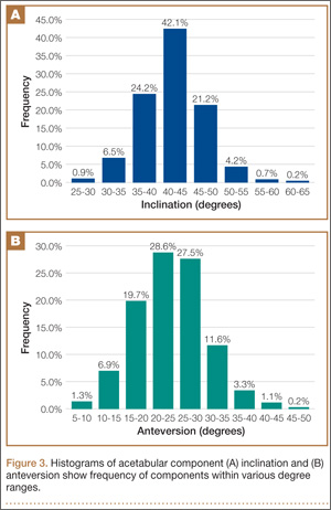
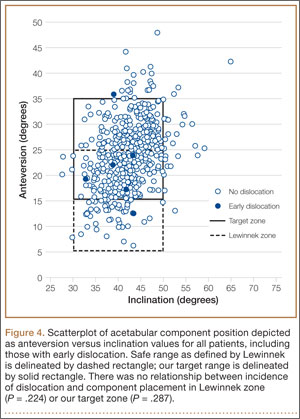
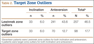
Regression analysis was performed separately for inclination and anteversion to determine the risk factors for placing the acetabular component outside the target orientation ranges. Only higher BMI was associated with malposition with respect to inclination (hazard ratio [HR], 1.059; 95% confidence interval [CI], 1.011-1.111; P = .017). Of obese patients with inclination outside the target range, 90.9% had an inclination angle of more than 50°. Associations between inclination outside the target range and age (P = .769), sex (P = .217), preoperative diagnosis (P > .99), and laterality (P = .106) were statistically insignificant. Only female sex was associated with position of the acetabular component outside the target range for anteversion (HR, 1.871; 95% CI, 1.061-3.299; P = .030). Of female patients with anteversion outside the target range, 70.0% had anteversion of less than 15°. Associations between anteversion outside the target range and age (P = .762), BMI (P = .583), preoperative diagnosis (P > .99), and laterality (P = .235) were statistically insignificant.
Six THAs (1.1%) in 6 patients experienced dislocation within 6 months after surgery (Table 3); mean (SD) time of dislocation was 58.3 (13.8) days after surgery. There was no relationship between dislocation incidence and component placement in the Lewinnek zone (P = .224) or our target zone (P = .287). Of the dislocation cases, 50% involved female patients, and 50% involved right hips. Mean (SD) age of these patients was 53.3 (7.6) years. Mean (SD) BMI was 25.4 (0.9) kg/m2. Osteoarthritis was the primary diagnosis for all patients with early dislocation; 32- or 36-mm femoral heads were used in these cases. Two patients had acetabular components placed outside of our target zone. One patient, who had abnormal pelvic obliquity and sagittal tilt from scoliosis (Figures 5A, 5B), had an acetabular component placed outside both the target zone and the Lewinnek safe zone. Mean (SD) acetabular inclination was 39.8° (3.6°), and mean (SD) anteversion was 21.8° (7.3°) (Figure 5C). Two dislocations resulted from trauma, 1 dislocation was related to hyperlaxity, 1 patient had cerebral palsy, and 1 patient had no evident predisposing risk factors. Three patients (0.54%) had multiple episodes of instability requiring revision during the follow-up period.
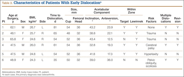
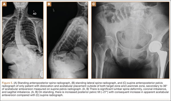
Discussion
To our knowledge, this study represents the largest cohort of primary THAs performed with an imageless navigation system. Our results showed that increasing targeted acetabular anteversion to 25° using a posterolateral surgical approach and modern implants resulted in a 1.1% incidence of early dislocation and a 0.54% incidence of recurrent instability requiring reoperation. Of the patients with a dislocation, only 1 did not experience trauma and did not have a risk factor for dislocation. Only 1 patient with a dislocation had acetabular components positioned outside both the target zone and the Lewinnek safe zone. The acetabular component was placed within the target zone in 82.3% of cases in which the imageless navigation system was used. In our cohort, BMI was the only risk factor for placement of the acetabular component outside our target range for inclination, and sex was associated with components outside the target range for anteversion.
Early dislocation after THA is often related to improper implant orientation, inadequate restoration of offset and myofascial tension, and decreased femoral head–neck ratio.8 Although dislocation rates in the literature vary widely,1,2 Medicare data suggest that the rate for the first 6 months after surgery can be as high as 4.21%.3,4 Although use of femoral heads with a diameter of 32 mm or larger may decrease this rate to 2.14%,3 accurate acetabular component orientation helps prevent postoperative dislocation.10 Using an imageless navigation system to target 25° of anteversion and 40° of inclination resulted in an early-dislocation rate about 49% less than the rate in a Medicare population treated with similar, modern implants.3
Callanan and colleagues11 found that freehand techniques were inaccurate for acetabular positioning in up to 50% of cases, and several studies have demonstrated that imageless navigation systems were more accurate than conventional guides.20,21,27-29 Higher BMI has been implicated as a risk factor for acetabular malpositioning in several studies of the accuracy of freehand techniques11 and imageless navigation techniques.23,30 Soft-tissue impediment to the component insertion handle poses a risk of increased inclination and inadequate anteversion, regardless of method used (conventional, CAS). When the acetabular component is placed freehand in obese patients, it is difficult to judge the position of the pelvis on the operating room table. For imageless navigation, a larger amount of adipose tissue over bony landmarks may limit the accuracy of anterior pelvic plane registration.30 Sex typically is not cited as a risk factor for inaccurate acetabular component positioning. We speculate that omitted-variable bias may explain the observed association between female sex and anteversion. For example, changes in postoperative pelvic tilt alter apparent anteversion on plain radiographs,31-34 but preoperative and postoperative sagittal pelvic tilt was not recorded in this study.
The proper position of the acetabular component has been debated.15,16,35,36 Although it is generally agreed that inclination of 40° ± 10° balances ROM, stability, and bearing-surface wear,12,13,15,16 proposed targets for anteversion vary widely, from 0° to 40°.35,36 Patel and colleagues16 formulated computer models based on cadaveric specimens to determine that THA impingement was minimized when the acetabular component was placed to match the native anteversion of the acetabulum.In their study model, 20° of anteversion paralleled native acetabular orientation. Tohtz and colleagues18 reviewed computed tomography scans of 144 female hips and 192 male hips and found that mean (SD) anteversion was 24.6° (6.6°) for women and 21.3° (6.2°) for men. Whether native anatomy is a valid reference for acetabular anteversion is controversial,19 and definitive recommendations for target anteversion cannot be made, as the effect of acetabular anteversion on the wear of various bearing materials is unknown.14 Yet, as with inclination, ideal anteversion is likely a compromise between maximizing impingement-free ROM and minimizing wear.
The present study had several limitations. A single-surgeon patient series was reviewed retrospectively, and there was no control group. We determined the incidence only of early dislocation, and 5.3% of THAs that were not metal-on-metal were either lost to follow-up or had inadequate radiographs. However, of the patients excluded for inadequate radiographs, none had an early dislocation. The effects of our surgical techniques on long-term outcomes, bearing wear, and dislocation are unknown. We were not able to comment on the direction of dislocation for any of the 6 patients with early dislocation, as all dislocations were reduced at facilities other than our hospital. Therefore, we cannot determine whether increasing acetabular anteversion resulted in a larger number of anterior versus posterior dislocations.15
We did not use CAS to place any of the femoral components. Therefore, we could not accurately target combined anteversion, defined as the sum of acetabular and femoral version, which may be an important determinant of THA stability.28 Although restoration of femoral offset and leg length is important in preventing THA dislocation,8 the CAS techniques used did not influence these parameters, and they were not measured.
As an imageless navigation system was used, there were no preoperative axial images, which could have been used to assess native acetabular orientation. This limited our assessment with respect to matching each patient’s natural anteversion. Imageless navigation, which references only the anterior pelvic plane, may not be reliable in patients with excessive sagittal pelvic tilt.37 Furthermore, changes in the functional position of the pelvis from supine to sitting to standing were not accounted for, and changes in sagittal tilt between these positions can be significant.38 Changes in sagittal pelvic tilt affect measurement of acetabular anteversion on plain radiographs, with anterior tilt reducing apparent anteversion and posterior tilt increasing it.32,34 Although postoperative computed tomography is the gold standard for assessing acetabular component orientation, EBRA significantly reduces errors of measurement on plain radiographs.10 Some variability in measured anteversion may be explained by our surgical technique. In particular, if the cup was uncovered anteriorly, additional anteversion was usually accepted during surgery to minimize anterior impingement and limit the risk of iliopsoas tendonitis.16,39
Our study results suggested that increasing target acetabular anteversion to 25° may reduce the incidence of early postoperative instability relative to rates reported in the literature. Despite the higher accuracy of component placement with an imageless navigation system, dislocations occurred in patients with acetabular components positioned in our target zone and in the historical safe zone. These dislocations support the notion that there likely is no absolute safe range for acetabular component positioning, as THA stability depends on many factors. Ideal targets for implant orientation for acetabulum and femur may be patient-specific.16,19 Investigators should prospectively evaluate patient-specific THA component positioning and determine its effect on postoperative dislocation and bearing-surface wear. As specific implant targets are further defined, tools that are more precise and accurate than conventional techniques will be needed to achieve goal component positioning. Our study results confirmed that imageless navigation is an accurate method for achieving acetabular orientation targets.
1. Kwon MS, Kuskowski M, Mulhall KJ, Macaulay W, Brown TE, Saleh KJ. Does surgical approach affect total hip arthroplasty dislocation rates? Clin Orthop. 2006;(447):34-38.
2. Sierra RJ, Raposo JM, Trousdale RT, Cabanela ME. Dislocation of primary THA done through a posterolateral approach in the elderly. Clin Orthop. 2005;(441):262-267.
3. Malkani AL, Ong KL, Lau E, Kurtz SM, Justice BJ, Manley MT. Early- and late-term dislocation risk after primary hip arthroplasty in the Medicare population. J Arthroplasty. 2010;25(6 suppl):21-25.
4. Berry DJ, von Knoch M, Schleck CD, Harmsen WS. Effect of femoral head diameter and operative approach on risk of dislocation after primary total hip arthroplasty. J Bone Joint Surg Am. 2005;87(11):2456-2463.
5. Nho SJ, Kymes SM, Callaghan JJ, Felson DT. The burden of hip osteoarthritis in the United States: epidemiologic and economic considerations. J Am Acad Orthop Surg. 2013;21(suppl 1):S1-S6.
6. Sadr Azodi O, Adami J, Lindstrom D, Eriksson KO, Wladis A, Bellocco R. High body mass index is associated with increased risk of implant dislocation following primary total hip replacement: 2,106 patients followed for up to 8 years. Acta Orthop. 2008;79(1):141-147.
7. Conroy JL, Whitehouse SL, Graves SE, Pratt NL, Ryan P, Crawford RW. Risk factors for revision for early dislocation in total hip arthroplasty. J Arthroplasty. 2008;23(6):867-872.
8. Morrey BF. Difficult complications after hip joint replacement. Dislocation. Clin Orthop. 1997;(344):179-187.
9. Ho KW, Whitwell GS, Young SK. Reducing the rate of early primary hip dislocation by combining a change in surgical technique and an increase in femoral head diameter to 36 mm. Arch Orthop Trauma Surg. 2012;132(7):1031-1036.
10. Biedermann R, Tonin A, Krismer M, Rachbauer F, Eibl G, Stockl B. Reducing the risk of dislocation after total hip arthroplasty: the effect of orientation of the acetabular component. J Bone Joint Surg Br. 2005;87(6):762-769.
11. Callanan MC, Jarrett B, Bragdon CR, et al. The John Charnley Award: risk factors for cup malpositioning: quality improvement through a joint registry at a tertiary hospital. Clin Orthop. 2011;469(2):319-329.
12. Gallo J, Havranek V, Zapletalova J. Risk factors for accelerated polyethylene wear and osteolysis in ABG I total hip arthroplasty. Int Orthop. 2010;34(1):19-26.
13. Leslie IJ, Williams S, Isaac G, Ingham E, Fisher J. High cup angle and microseparation increase the wear of hip surface replacements. Clin Orthop. 2009;467(9):2259-2265.
14. Esposito CI, Walter WL, Roques A, et al. Wear in alumina-on-alumina ceramic total hip replacements: a retrieval analysis of edge loading. J Bone Joint Surg Br. 2012;94(7):901-907.
15. Lewinnek GE, Lewis JL, Tarr R, Compere CL, Zimmerman JR. Dislocations after total hip-replacement arthroplasties. J Bone Joint Surg Am. 1978;60(2):217-220.
16. Patel AB, Wagle RR, Usrey MM, Thompson MT, Incavo SJ, Noble PC. Guidelines for implant placement to minimize impingement during activities of daily living after total hip arthroplasty. J Arthroplasty. 2010;25(8):1275-1281.e1.
17. Widmer KH, Zurfluh B. Compliant positioning of total hip components for optimal range of motion. J Orthop Res. 2004;22(4):815-821.
18. Tohtz SW, Sassy D, Matziolis G, Preininger B, Perka C, Hasart O. CT evaluation of native acetabular orientation and localization: sex-specific data comparison on 336 hip joints. Technol Health Care. 2010;18(2):129-136.
19. Merle C, Grammatopoulos G, Waldstein W, et al. Comparison of native anatomy with recommended safe component orientation in total hip arthroplasty for primary osteoarthritis. J Bone Joint Surg Am. 2013;95(22):e172.
20. Nogler M, Kessler O, Prassl A, et al. Reduced variability of acetabular cup positioning with use of an imageless navigation system. Clin Orthop. 2004;(426):159-163.
21. Wixson RL, MacDonald MA. Total hip arthroplasty through a minimal posterior approach using imageless computer-assisted hip navigation. J Arthroplasty. 2005;20(7 suppl 3):51-56.
22. Jolles BM, Genoud P, Hoffmeyer P. Computer-assisted cup placement techniques in total hip arthroplasty improve accuracy of placement. Clin Orthop. 2004;(426):174-179.
23. Lass R, Kubista B, Olischar B, Frantal S, Windhager R, Giurea A. Total hip arthroplasty using imageless computer-assisted hip navigation: a prospective randomized study. J Arthroplasty. 2014;29(4):786-791.
24. Babisch JW, Layher F, Amiot LP. The rationale for tilt-adjusted acetabular cup navigation. J Bone Joint Surg Am. 2008;90(2):357-365.
25. Pellicci PM, Bostrom M, Poss R. Posterior approach to total hip replacement using enhanced posterior soft tissue repair. Clin Orthop. 1998;(355):224-228.
26. Krismer M, Bauer R, Tschupik J, Mayrhofer P. EBRA: a method to measure migration of acetabular components. J Biomech. 1995;28(10):1225-1236.
27. Parratte S, Argenson JN. Validation and usefulness of a computer-assisted cup-positioning system in total hip arthroplasty. A prospective, randomized, controlled study. J Bone Joint Surg Am. 2007;89(3):494-499.
28. Dorr LD, Malik A, Wan Z, Long WT, Harris M. Precision and bias of imageless computer navigation and surgeon estimates for acetabular component position. Clin Orthop. 2007;(465):92-99.
29. Najarian BC, Kilgore JE, Markel DC. Evaluation of component positioning in primary total hip arthroplasty using an imageless navigation device compared with traditional methods. J Arthroplasty. 2009;24(1):15-21.
30. Hohmann E, Bryant A, Tetsworth K. Anterior pelvic soft tissue thickness influences acetabular cup positioning with imageless navigation. J Arthroplasty. 2012;27(6):945-952.
31. Nguyen AD, Shultz SJ. Sex differences in clinical measures of lower extremity alignment. J Orthop Sports Phys Ther. 2007;37(7):389-398.
32. Malik A, Wan Z, Jaramaz B, Bowman G, Dorr LD. A validation model for measurement of acetabular component position. J Arthroplasty. 2010;25(5):812-819.
33. Tannast M, Murphy SB, Langlotz F, Anderson SE, Siebenrock KA. Estimation of pelvic tilt on anteroposterior X-rays—a comparison of six parameters. Skeletal Radiol. 2006;35(3):149-155.
34. Parratte S, Pagnano MW, Coleman-Wood K, Kaufman KR, Berry DJ. The 2008 Frank Stinchfield Award: variation in postoperative pelvic tilt may confound the accuracy of hip navigation systems. Clin Orthop. 2009;467(1):43-49.
35. McCollum DE, Gray WJ. Dislocation after total hip arthroplasty. Causes and prevention. Clin Orthop. 1990;(261):159-170.
36. Kummer FJ, Shah S, Iyer S, DiCesare PE. The effect of acetabular cup orientations on limiting hip rotation. J Arthroplasty. 1999;14(4):509-513.
37. Lin F, Lim D, Wixson RL, Milos S, Hendrix RW, Makhsous M. Limitations of imageless computer-assisted navigation for total hip arthroplasty. J Arthroplasty. 2011;26(4):596-605.
38. Lazennec JY, Riwan A, Gravez F, et al. Hip spine relationships: application to total hip arthroplasty. Hip Int. 2007;17(suppl 5):S91-S104.
39. Trousdale RT, Cabanela ME, Berry DJ. Anterior iliopsoas impingement after total hip arthroplasty. J Arthroplasty. 1995;10(4):546-549.
Postoperative dislocation remains a common complication of primary total hip arthroplasties (THAs), affecting less than 1% to more than 10% in reported series.1,2 In large datasets for modern implants, the incidence of dislocation is 2% to 4%.3,4 Given that more than 200,000 THAs are performed in the United States each year,5 these low percentages represent a large number of patients. The multiplex patient variables that affect THA stability include age, sex, body mass index (BMI), and comorbid conditions.6-8 Surgical approach, restoration of leg length and femoral offset, femoral head size, and component positioning are also important surgical factors that can increase or decrease the incidence of dislocation.3,8,9 In particular, appropriate acetabular component orientation is crucial; surgeons can control this factor and thereby limit the occurrence of dislocation.10 Furthermore, acetabular malpositioning can increase the risk of liner fractures and accelerate bearing-surface wear.11-14
To minimize the risk of postoperative dislocation, surgeons traditionally have targeted the Lewinnek safe zone, with its mean (SD) inclination of 40° (10°) and mean (SD) anteversion of 15° (10°), for acetabular component orientation.15 However, the applicability of this target zone to preventing hip instability using modern implant designs, components, and surgical techniques remains unknown. Achieving acetabular orientation based on maximizing range of motion (ROM) before impingement may be optimal, with anteversion from 20° to 30° and inclination from 40° to 45°.16,17 Furthermore, mean (SD) native acetabular anteversion ranges from 21.3° (6.2°) for men to 24.6° (6.6°) for women.18 Placing THA acetabular components near the native range for anteversion may best provide impingement-free ROM and thus optimize THA stability,16,19 but this has not been proved in a clinical study.
Early dislocation is typically classified as occurring within 6 months after surgery,9 with almost 80% of dislocations occurring within 3 months after surgery.10 Surgeon-specific factors, such as acetabular component positioning, are thought to have a predominant effect on dislocations in the early postoperative period.10 Computer-assisted surgery (CAS), such as imageless navigation, is more accurate than conventional methods for acetabular component placement,20-23 but the clinical relevance of improving accuracy for acetabular component placement has not been shown with respect to altering patient outcomes.23
We conducted a study in a large single-surgeon patient cohort to determine the incidence of early postoperative dislocation with target anteversion increased to 25°, approximating mean native acetabular anteversion.16,19 In addition, we sought to determine the accuracy of imageless navigation in achieving target acetabular component placement.
Materials and Methods
After obtaining institutional review board approval for this retrospective clinical study, we reviewed 671 consecutive cases of primary THA performed by a single surgeon using an imageless CAS system (AchieveCAS; Smith & Nephew, Memphis, Tennessee) between July 2006 and October 2012. THAs were excluded if a metal-on-metal bearing surface was used, if an adequate 6-week postoperative supine anteroposterior (AP) pelvis radiograph was unavailable, or if 6-month clinical follow-up findings were not available (Figure 1). The quality of AP radiographs was deemed poor if they were not centered on the symphysis pubis and if the sacrococcygeal joint was not centered over the symphysis pubis. After exclusion criteria were applied, 553 arthroplasties (479 patients) with a mean (SD) follow-up of 2.4 (1.4) years remained. Perioperative demographic data and component sizes are listed in Table 1.
During surgery, the anterior pelvic plane, defined by the anterior-superior iliac spines and pubic tubercle, was registered with the CAS system with the patient in the supine position. THA was performed with the patient in the lateral decubitus position using a posterolateral technique. For all patients, the surgeon used a hemispherical acetabular component (R3 Acetabular System; Smith & Nephew); bearings that were either metal on highly cross-linked polyethylene (XLPE) or Oxinium (Smith & Nephew) on XLPE; and neutral XLPE acetabular inserts. The goals for acetabular inclination and anteversion were 40° and 25°, respectively, with ±10° each for the target zone. The CAS system was used to adjust target anteversion for sagittal pelvic tilt.24 Uncemented femoral components were used for all patients, and the goal for femoral component anteversion was 15°. Transosseous repair of the posterior capsule and short external rotators was performed after component implantation.25
On each 6-week postoperative radiograph, acetabular orientation was measured with Ein-Bild-Röntgen-Analyse (EBRA; University of Innsbruck, Austria) software, which provides a validated method for measuring acetabular inclination and anteversion on supine AP pelvis radiographs.10,26 Pelvic boundaries were delineated with grid lines defining pelvic position. Reference points around the projections of the prosthetic femoral head, the hemispherical cup, and the rim of the cup were marked (Figure 2). EBRA calculated radiographic inclination and anteversion of the acetabular component based on the spatial position of the cup center in relation to the plane of the radiograph and the pelvic position.26
Charts were reviewed to identify patients with early postoperative dislocations, as well as dislocation timing, recurrence, and other characteristics. We defined early dislocation as instability occurring within 6 months after surgery. Revision surgery for instability was also identified.
For the statistical analysis, orientation error was defined as the absolute value of the difference between target orientation (40° inclination, 25° anteversion) and radiographic measurements. Repeated-measures multiple regression with the generalized estimating equations approach was used to identify baseline patient characteristics (age, sex, BMI, primary diagnosis, laterality) associated with component positioning outside of our targeted ranges for inclination and anteversion. Fisher exact tests were used to examine the relationship between dislocation and component placement in either the Lewinnek safe zone or our targeted zone. All tests were 2-sided with a significance level of .05. All analyses were performed with SAS for Windows 9.3 (SAS Institute, Cary, North Carolina).
Results
Mean (SD) acetabular inclination was 42.2° (4.9°) (range, 27.6°-65.0°), with a mean (SD) orientation error of 4.2° (3.4°) (Figure 3A). Mean (SD) anteversion was 23.9° (6.5°) (range, 6.2°-48.0°), with a mean (SD) orientation error of 5.2° (4.1°) (Figure 3B). Components were placed outside the Lewinnek safe zone for inclination or anteversion in 46.5% of cases and outside the target zone in 17.7% of cases (Figure 4). Variation in acetabular anteversion alone accounted for 67.3% of target zone outliers (Table 2). Only 0.9% of components were placed outside the target ranges for both inclination and anteversion.
Regression analysis was performed separately for inclination and anteversion to determine the risk factors for placing the acetabular component outside the target orientation ranges. Only higher BMI was associated with malposition with respect to inclination (hazard ratio [HR], 1.059; 95% confidence interval [CI], 1.011-1.111; P = .017). Of obese patients with inclination outside the target range, 90.9% had an inclination angle of more than 50°. Associations between inclination outside the target range and age (P = .769), sex (P = .217), preoperative diagnosis (P > .99), and laterality (P = .106) were statistically insignificant. Only female sex was associated with position of the acetabular component outside the target range for anteversion (HR, 1.871; 95% CI, 1.061-3.299; P = .030). Of female patients with anteversion outside the target range, 70.0% had anteversion of less than 15°. Associations between anteversion outside the target range and age (P = .762), BMI (P = .583), preoperative diagnosis (P > .99), and laterality (P = .235) were statistically insignificant.
Six THAs (1.1%) in 6 patients experienced dislocation within 6 months after surgery (Table 3); mean (SD) time of dislocation was 58.3 (13.8) days after surgery. There was no relationship between dislocation incidence and component placement in the Lewinnek zone (P = .224) or our target zone (P = .287). Of the dislocation cases, 50% involved female patients, and 50% involved right hips. Mean (SD) age of these patients was 53.3 (7.6) years. Mean (SD) BMI was 25.4 (0.9) kg/m2. Osteoarthritis was the primary diagnosis for all patients with early dislocation; 32- or 36-mm femoral heads were used in these cases. Two patients had acetabular components placed outside of our target zone. One patient, who had abnormal pelvic obliquity and sagittal tilt from scoliosis (Figures 5A, 5B), had an acetabular component placed outside both the target zone and the Lewinnek safe zone. Mean (SD) acetabular inclination was 39.8° (3.6°), and mean (SD) anteversion was 21.8° (7.3°) (Figure 5C). Two dislocations resulted from trauma, 1 dislocation was related to hyperlaxity, 1 patient had cerebral palsy, and 1 patient had no evident predisposing risk factors. Three patients (0.54%) had multiple episodes of instability requiring revision during the follow-up period.
Discussion
To our knowledge, this study represents the largest cohort of primary THAs performed with an imageless navigation system. Our results showed that increasing targeted acetabular anteversion to 25° using a posterolateral surgical approach and modern implants resulted in a 1.1% incidence of early dislocation and a 0.54% incidence of recurrent instability requiring reoperation. Of the patients with a dislocation, only 1 did not experience trauma and did not have a risk factor for dislocation. Only 1 patient with a dislocation had acetabular components positioned outside both the target zone and the Lewinnek safe zone. The acetabular component was placed within the target zone in 82.3% of cases in which the imageless navigation system was used. In our cohort, BMI was the only risk factor for placement of the acetabular component outside our target range for inclination, and sex was associated with components outside the target range for anteversion.
Early dislocation after THA is often related to improper implant orientation, inadequate restoration of offset and myofascial tension, and decreased femoral head–neck ratio.8 Although dislocation rates in the literature vary widely,1,2 Medicare data suggest that the rate for the first 6 months after surgery can be as high as 4.21%.3,4 Although use of femoral heads with a diameter of 32 mm or larger may decrease this rate to 2.14%,3 accurate acetabular component orientation helps prevent postoperative dislocation.10 Using an imageless navigation system to target 25° of anteversion and 40° of inclination resulted in an early-dislocation rate about 49% less than the rate in a Medicare population treated with similar, modern implants.3
Callanan and colleagues11 found that freehand techniques were inaccurate for acetabular positioning in up to 50% of cases, and several studies have demonstrated that imageless navigation systems were more accurate than conventional guides.20,21,27-29 Higher BMI has been implicated as a risk factor for acetabular malpositioning in several studies of the accuracy of freehand techniques11 and imageless navigation techniques.23,30 Soft-tissue impediment to the component insertion handle poses a risk of increased inclination and inadequate anteversion, regardless of method used (conventional, CAS). When the acetabular component is placed freehand in obese patients, it is difficult to judge the position of the pelvis on the operating room table. For imageless navigation, a larger amount of adipose tissue over bony landmarks may limit the accuracy of anterior pelvic plane registration.30 Sex typically is not cited as a risk factor for inaccurate acetabular component positioning. We speculate that omitted-variable bias may explain the observed association between female sex and anteversion. For example, changes in postoperative pelvic tilt alter apparent anteversion on plain radiographs,31-34 but preoperative and postoperative sagittal pelvic tilt was not recorded in this study.
The proper position of the acetabular component has been debated.15,16,35,36 Although it is generally agreed that inclination of 40° ± 10° balances ROM, stability, and bearing-surface wear,12,13,15,16 proposed targets for anteversion vary widely, from 0° to 40°.35,36 Patel and colleagues16 formulated computer models based on cadaveric specimens to determine that THA impingement was minimized when the acetabular component was placed to match the native anteversion of the acetabulum.In their study model, 20° of anteversion paralleled native acetabular orientation. Tohtz and colleagues18 reviewed computed tomography scans of 144 female hips and 192 male hips and found that mean (SD) anteversion was 24.6° (6.6°) for women and 21.3° (6.2°) for men. Whether native anatomy is a valid reference for acetabular anteversion is controversial,19 and definitive recommendations for target anteversion cannot be made, as the effect of acetabular anteversion on the wear of various bearing materials is unknown.14 Yet, as with inclination, ideal anteversion is likely a compromise between maximizing impingement-free ROM and minimizing wear.
The present study had several limitations. A single-surgeon patient series was reviewed retrospectively, and there was no control group. We determined the incidence only of early dislocation, and 5.3% of THAs that were not metal-on-metal were either lost to follow-up or had inadequate radiographs. However, of the patients excluded for inadequate radiographs, none had an early dislocation. The effects of our surgical techniques on long-term outcomes, bearing wear, and dislocation are unknown. We were not able to comment on the direction of dislocation for any of the 6 patients with early dislocation, as all dislocations were reduced at facilities other than our hospital. Therefore, we cannot determine whether increasing acetabular anteversion resulted in a larger number of anterior versus posterior dislocations.15
We did not use CAS to place any of the femoral components. Therefore, we could not accurately target combined anteversion, defined as the sum of acetabular and femoral version, which may be an important determinant of THA stability.28 Although restoration of femoral offset and leg length is important in preventing THA dislocation,8 the CAS techniques used did not influence these parameters, and they were not measured.
As an imageless navigation system was used, there were no preoperative axial images, which could have been used to assess native acetabular orientation. This limited our assessment with respect to matching each patient’s natural anteversion. Imageless navigation, which references only the anterior pelvic plane, may not be reliable in patients with excessive sagittal pelvic tilt.37 Furthermore, changes in the functional position of the pelvis from supine to sitting to standing were not accounted for, and changes in sagittal tilt between these positions can be significant.38 Changes in sagittal pelvic tilt affect measurement of acetabular anteversion on plain radiographs, with anterior tilt reducing apparent anteversion and posterior tilt increasing it.32,34 Although postoperative computed tomography is the gold standard for assessing acetabular component orientation, EBRA significantly reduces errors of measurement on plain radiographs.10 Some variability in measured anteversion may be explained by our surgical technique. In particular, if the cup was uncovered anteriorly, additional anteversion was usually accepted during surgery to minimize anterior impingement and limit the risk of iliopsoas tendonitis.16,39
Our study results suggested that increasing target acetabular anteversion to 25° may reduce the incidence of early postoperative instability relative to rates reported in the literature. Despite the higher accuracy of component placement with an imageless navigation system, dislocations occurred in patients with acetabular components positioned in our target zone and in the historical safe zone. These dislocations support the notion that there likely is no absolute safe range for acetabular component positioning, as THA stability depends on many factors. Ideal targets for implant orientation for acetabulum and femur may be patient-specific.16,19 Investigators should prospectively evaluate patient-specific THA component positioning and determine its effect on postoperative dislocation and bearing-surface wear. As specific implant targets are further defined, tools that are more precise and accurate than conventional techniques will be needed to achieve goal component positioning. Our study results confirmed that imageless navigation is an accurate method for achieving acetabular orientation targets.
1. Kwon MS, Kuskowski M, Mulhall KJ, Macaulay W, Brown TE, Saleh KJ. Does surgical approach affect total hip arthroplasty dislocation rates? Clin Orthop. 2006;(447):34-38.
2. Sierra RJ, Raposo JM, Trousdale RT, Cabanela ME. Dislocation of primary THA done through a posterolateral approach in the elderly. Clin Orthop. 2005;(441):262-267.
3. Malkani AL, Ong KL, Lau E, Kurtz SM, Justice BJ, Manley MT. Early- and late-term dislocation risk after primary hip arthroplasty in the Medicare population. J Arthroplasty. 2010;25(6 suppl):21-25.
4. Berry DJ, von Knoch M, Schleck CD, Harmsen WS. Effect of femoral head diameter and operative approach on risk of dislocation after primary total hip arthroplasty. J Bone Joint Surg Am. 2005;87(11):2456-2463.
5. Nho SJ, Kymes SM, Callaghan JJ, Felson DT. The burden of hip osteoarthritis in the United States: epidemiologic and economic considerations. J Am Acad Orthop Surg. 2013;21(suppl 1):S1-S6.
6. Sadr Azodi O, Adami J, Lindstrom D, Eriksson KO, Wladis A, Bellocco R. High body mass index is associated with increased risk of implant dislocation following primary total hip replacement: 2,106 patients followed for up to 8 years. Acta Orthop. 2008;79(1):141-147.
7. Conroy JL, Whitehouse SL, Graves SE, Pratt NL, Ryan P, Crawford RW. Risk factors for revision for early dislocation in total hip arthroplasty. J Arthroplasty. 2008;23(6):867-872.
8. Morrey BF. Difficult complications after hip joint replacement. Dislocation. Clin Orthop. 1997;(344):179-187.
9. Ho KW, Whitwell GS, Young SK. Reducing the rate of early primary hip dislocation by combining a change in surgical technique and an increase in femoral head diameter to 36 mm. Arch Orthop Trauma Surg. 2012;132(7):1031-1036.
10. Biedermann R, Tonin A, Krismer M, Rachbauer F, Eibl G, Stockl B. Reducing the risk of dislocation after total hip arthroplasty: the effect of orientation of the acetabular component. J Bone Joint Surg Br. 2005;87(6):762-769.
11. Callanan MC, Jarrett B, Bragdon CR, et al. The John Charnley Award: risk factors for cup malpositioning: quality improvement through a joint registry at a tertiary hospital. Clin Orthop. 2011;469(2):319-329.
12. Gallo J, Havranek V, Zapletalova J. Risk factors for accelerated polyethylene wear and osteolysis in ABG I total hip arthroplasty. Int Orthop. 2010;34(1):19-26.
13. Leslie IJ, Williams S, Isaac G, Ingham E, Fisher J. High cup angle and microseparation increase the wear of hip surface replacements. Clin Orthop. 2009;467(9):2259-2265.
14. Esposito CI, Walter WL, Roques A, et al. Wear in alumina-on-alumina ceramic total hip replacements: a retrieval analysis of edge loading. J Bone Joint Surg Br. 2012;94(7):901-907.
15. Lewinnek GE, Lewis JL, Tarr R, Compere CL, Zimmerman JR. Dislocations after total hip-replacement arthroplasties. J Bone Joint Surg Am. 1978;60(2):217-220.
16. Patel AB, Wagle RR, Usrey MM, Thompson MT, Incavo SJ, Noble PC. Guidelines for implant placement to minimize impingement during activities of daily living after total hip arthroplasty. J Arthroplasty. 2010;25(8):1275-1281.e1.
17. Widmer KH, Zurfluh B. Compliant positioning of total hip components for optimal range of motion. J Orthop Res. 2004;22(4):815-821.
18. Tohtz SW, Sassy D, Matziolis G, Preininger B, Perka C, Hasart O. CT evaluation of native acetabular orientation and localization: sex-specific data comparison on 336 hip joints. Technol Health Care. 2010;18(2):129-136.
19. Merle C, Grammatopoulos G, Waldstein W, et al. Comparison of native anatomy with recommended safe component orientation in total hip arthroplasty for primary osteoarthritis. J Bone Joint Surg Am. 2013;95(22):e172.
20. Nogler M, Kessler O, Prassl A, et al. Reduced variability of acetabular cup positioning with use of an imageless navigation system. Clin Orthop. 2004;(426):159-163.
21. Wixson RL, MacDonald MA. Total hip arthroplasty through a minimal posterior approach using imageless computer-assisted hip navigation. J Arthroplasty. 2005;20(7 suppl 3):51-56.
22. Jolles BM, Genoud P, Hoffmeyer P. Computer-assisted cup placement techniques in total hip arthroplasty improve accuracy of placement. Clin Orthop. 2004;(426):174-179.
23. Lass R, Kubista B, Olischar B, Frantal S, Windhager R, Giurea A. Total hip arthroplasty using imageless computer-assisted hip navigation: a prospective randomized study. J Arthroplasty. 2014;29(4):786-791.
24. Babisch JW, Layher F, Amiot LP. The rationale for tilt-adjusted acetabular cup navigation. J Bone Joint Surg Am. 2008;90(2):357-365.
25. Pellicci PM, Bostrom M, Poss R. Posterior approach to total hip replacement using enhanced posterior soft tissue repair. Clin Orthop. 1998;(355):224-228.
26. Krismer M, Bauer R, Tschupik J, Mayrhofer P. EBRA: a method to measure migration of acetabular components. J Biomech. 1995;28(10):1225-1236.
27. Parratte S, Argenson JN. Validation and usefulness of a computer-assisted cup-positioning system in total hip arthroplasty. A prospective, randomized, controlled study. J Bone Joint Surg Am. 2007;89(3):494-499.
28. Dorr LD, Malik A, Wan Z, Long WT, Harris M. Precision and bias of imageless computer navigation and surgeon estimates for acetabular component position. Clin Orthop. 2007;(465):92-99.
29. Najarian BC, Kilgore JE, Markel DC. Evaluation of component positioning in primary total hip arthroplasty using an imageless navigation device compared with traditional methods. J Arthroplasty. 2009;24(1):15-21.
30. Hohmann E, Bryant A, Tetsworth K. Anterior pelvic soft tissue thickness influences acetabular cup positioning with imageless navigation. J Arthroplasty. 2012;27(6):945-952.
31. Nguyen AD, Shultz SJ. Sex differences in clinical measures of lower extremity alignment. J Orthop Sports Phys Ther. 2007;37(7):389-398.
32. Malik A, Wan Z, Jaramaz B, Bowman G, Dorr LD. A validation model for measurement of acetabular component position. J Arthroplasty. 2010;25(5):812-819.
33. Tannast M, Murphy SB, Langlotz F, Anderson SE, Siebenrock KA. Estimation of pelvic tilt on anteroposterior X-rays—a comparison of six parameters. Skeletal Radiol. 2006;35(3):149-155.
34. Parratte S, Pagnano MW, Coleman-Wood K, Kaufman KR, Berry DJ. The 2008 Frank Stinchfield Award: variation in postoperative pelvic tilt may confound the accuracy of hip navigation systems. Clin Orthop. 2009;467(1):43-49.
35. McCollum DE, Gray WJ. Dislocation after total hip arthroplasty. Causes and prevention. Clin Orthop. 1990;(261):159-170.
36. Kummer FJ, Shah S, Iyer S, DiCesare PE. The effect of acetabular cup orientations on limiting hip rotation. J Arthroplasty. 1999;14(4):509-513.
37. Lin F, Lim D, Wixson RL, Milos S, Hendrix RW, Makhsous M. Limitations of imageless computer-assisted navigation for total hip arthroplasty. J Arthroplasty. 2011;26(4):596-605.
38. Lazennec JY, Riwan A, Gravez F, et al. Hip spine relationships: application to total hip arthroplasty. Hip Int. 2007;17(suppl 5):S91-S104.
39. Trousdale RT, Cabanela ME, Berry DJ. Anterior iliopsoas impingement after total hip arthroplasty. J Arthroplasty. 1995;10(4):546-549.
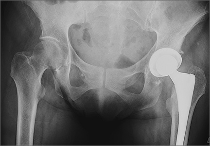
Leg-Length Discrepancy After Total Hip Arthroplasty: Comparison of Robot-Assisted Posterior, Fluoroscopy-Guided Anterior, and Conventional Posterior Approaches
Total hip arthroplasty (THA) effectively provides adequate pain relief and favorable outcomes in patients with hip osteoarthritis (OA). However, leg-length discrepancy (LLD) is still a significant cause of morbidity,1 including nerve damage,2,3 low back pain,2,4,5 and abnormal gait.2,6,7 Although most of the LLD values reported in the literature fall under the acceptable threshold of 10 mm,8 some patients report dissatisfaction,9 leading to litigation against orthopedic surgeons.2 However, lower extremity lengthening is sometimes needed to achieve adequate hip joint stability and prevent dislocations.2,10
Several methods have been developed to help surgeons estimate the change in leg length during surgery in an attempt to improve clinical outcomes. Use of guide pins as a reference on the pelvis decreased LLD and improved outcomes in some published studies.11,12 Preoperative templating of implant size, cup position, and level of femoral neck cut is very important in helping minimize clinically significant LLD after THA.2,13,14 Computer-assisted THA has also been introduced to try to improve component positioning, restoration of hip center of rotation, and minimizing of LLD.15-17 However, cost and increased operative time have prevented widespread adoption of computer-assisted surgery in THA.
Proponents of different surgical approaches have argued about the superiority of one approach over another. The posterior approach is the gold standard in THA because it is safe, easy to perform, and, if needed, extensile.11 However, exact determination of the intraoperative 3-dimensional (3-D) orientation of the pelvis, and subsequently of LLD, is challenging when the patient lies in the lateral position. The anterior approach has gained in popularity because of its advantages in accelerating postoperative rehabilitation and decreasing hospital length of stay.18 Placing the patient supine is advantageous because it allows leveling of the pelvis and estimation of LLD (by comparing the positions of the lower extremities).19 The anterior approach also allows for radiographic measurements on the operating table.19,20 However, this approach has a high learning curve21 and is not extensile.21 To date, no study has shown superiority of the anterior approach over either the conventional posterior approach or the robot-assisted posterior approach in minimizing LLD after THA.
We conducted a study to compare LLD in patients who underwent THA performed with a robot-assisted posterior approach (RTHA), a fluoroscopy-guided anterior approach (ATHA), or a conventional posterior approach (PTHA). We hypothesized that, compared with PTHA, both RTHA and ATHA would result in reduced LLD.
Materials and Methods
We reviewed all RTHAs, ATHAs, and PTHAs performed by Dr. Domb between September 2008 and December 2012. Study inclusion criteria were a diagnosis of hip OA and the availability of postoperative supine anteroposterior pelvis radiographs. Exclusion criteria were a diagnosis other than hip OA, missing or improper postoperative radiographs (radiographs with rotated or tilted pelvis),22 and radiographs on which at least one of the lesser trochanters was difficult to define. Of the 155 cases included in the study, 67 were RTHAs, 29 were ATHAs, and 59 were PTHAs.
All patients scheduled for THA underwent preoperative planning; plain radiographs were used to determine component size and position, level of neck cut, and amount of leg lengthening or shortening needed. In all RTHA cases, computed tomography of the involved hip was performed before surgery. The MAKO system (MAKO Surgical Corporation, Davie, Florida) was used to develop a patient-specific 3-D model of the pelvis and proximal femur, and this model was used to guide THA execution. The system was then used to detect patient-specific landmarks during surgery, to register the femur and the acetabulum, and to help determine the position of the pelvis and proximal femur during surgery. This system, which uses a haptic robotic arm that guides acetabular reaming and cup placement, provides feedback regarding cup placement, stem version, leg length, and global offset. Pelvic tilt and rotation were accounted for by the MAKO software, and all provided measurements were made on the coronal (functional) plane of the body, as described by Murray.23 ATHA was performed with the patient in the supine position on a Hana table (Mizuho OSI, Union City, California) with fluoroscopic guidance. PTHA was performed in the conventional way, with the patient in the lateral position.
Radiographic measurements of LLD were made with TraumaCad software (Build 2.2.535.0; Voyant Health, Petah-Tikva, Israel). The accuracy of this software has been studied and reported in the literature.24-26 Radiographs were calibrated using the known size of each femoral head as a marker. The reference on the pelvis was the interobturator line (line tangent to inferior border of obturator foramina), and the reference on the femurs was the most superior and medial aspect of each lesser trochanter. Two lines were drawn, each perpendicular to the interobturator line, starting from the previously defined reference point on each lesser trochanter. The difference in length between these 2 lines was recorded as the LLD. Values were recorded relative to the operative extremity. For example, if the operative extremity was longer than the nonoperative extremity, the LLD was given a positive value.
To eliminate bias and increase measurement accuracy, the study had each of 2 observers collect the LLD data twice, 2 months apart. These observers were blinded to each other’s results and to the type of surgery performed. (Neither observer was Dr. Domb, the senior surgeon.) IBM SPSS Statistics software (Version 20; IBM, Armonk, New York) was used for statistical analysis. Each patient’s 4 measurements were averaged into a single number for LLD, and the absolute LLD values were used in all statistical analyses. Means, standard deviations (SDs), and 95% confidence intervals (CIs) were calculated for LLD in each of the 3 groups. Pearson correlation coefficient was used to determine interobserver and intraobserver reliability. One-way analysis of variance (ANOVA) was used to compare group means for age, body mass index (BMI), and LLD. In each group, number of outliers was determined with outliers set at LLDs of more than 3 mm and more than 5 mm. Fischer exact test was used to compare number of outliers in each group. P < .05 was considered statistically significant.
Results
Table 1 lists the demographic data, including age, sex, and BMI, and compares the means. There were strong interobserver and intraobserver correlations for all LLD measurements (r > 0.9; P < .001). Mean (SD) LLD was 2.7 (1.8) mm (95% CI, 2.3-3.2) in the RTHA group, 1.8 (1.6) mm (95% CI, 1.2-2.4) in the ATHA group, and 1.9 (1.6) mm (95% CI, 1.5-2.4) in the PTHA group (P = .01). When LLD of more than 3 mm was set as an outlier, percentage of outliers was 37.3% (RTHA), 17.2% (ATHA), and 22% (PTHA) (P = .06-.78). When LLD of more than 5 mm was set as an outlier, percentage of outliers was 10.4% (RTHA), 6.9% (ATHA), and 8.5% (PTHA) (P = .72 to >.99). No patient in any group had LLD of 10 mm or more (Figure). Table 2 lists percentages of patients’ operated extremities that were longer, shorter, or the same size as their contralateral extremities. Six (9.0%) of the 67 RTHA patients, 4 (13.8%) of the 29 ATHA patients, and 3 (5.1%) of the 59 PTHA patients had a contralateral THA.
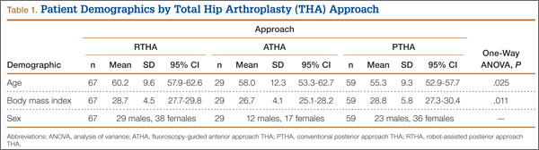
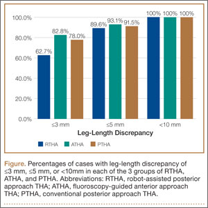
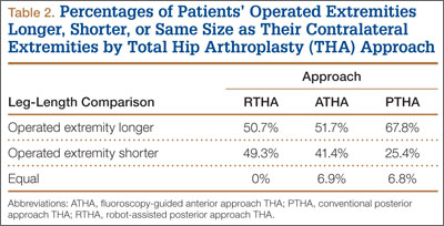
Discussion
Our study results showed that RTHA, ATHA, and PTHA were equally effective in minimizing LLD. There was a statistically significant difference in mean LLD among the 3 groups studied. The RTHA group had the largest mean (SD) LLD: 2.7 (1.8) mm. However, statistically significant differences do not always indicate clinical significance.27 Therefore, comparison of the 3 groups’ means is not enough for drawing significant conclusions. The more important point to consider is the number of cases of LLD of 10 mm or more—a discrepancy that would be perceptible to patients and thus become a source of dissatisfaction with painless THA.28 Patients perceive LLD when shortening exceeds 10 mm and lengthening exceeds 6 mm,29 or when LLD is more than 10 mm.16,19,20 Despite significant differences in means, all our cases came in under the 10-mm threshold. When the threshold was decreased to 5 mm (and to 3 mm), there was no statistically significant difference among the groups in the number of cases above the threshold.
LLD remains a source of significant post-THA comorbidity and patient dissatisfaction.1-7,19 Despite surgeons’ efforts to minimize LLD, some patients can detect even a subtle LLD after surgery.1,8,29 Most LLD values reported in the literature fall under the 10-mm threshold.16,19,20 In some cases, however, postoperative LLD is more than 1 cm, enough to prompt litigation against orthopedic surgeons.2 Surgeons have tried to improve LLD with use of multiple techniques, including use of intraoperative measuring devices,30 patient positioning during surgery,20 use of computer-assisted surgery,19 and use of intraoperative fluoroscopy.20
Proponents of computer-assisted THA have argued that this technique improves accuracy in placing the acetabular cup in the safe zone,31 minimizes LLD, and restores femoral offset.32,33 Manzotti and colleagues16 reported on 48 cases of computer-assisted THA matched to 48 cases of conventional THA using the posterior approach. Mean (SD) LLD was 5.06 (2.99) mm in the computer-assisted group and 7.64 (4.36) mm in the conventional group; there was a statistically significant difference in favor of the computer-assisted group (P = .04). However, 5 patients in the computer-assisted group and 13 in the conventional group had LLD of more than 10 mm, and the difference was statistically significant.16 Moreover, the study population was heterogeneous, with 12 patients in both groups having developmental dysplasia as a primary diagnosis.16 All the cases in our study had a diagnosis of OA, and no case had LLD of 10 mm or more.
Several advantages have been proposed for the anterior approach. The supine position (with direct comparison of leg lengths) and the use of fluoroscopy have been described as advantageous in minimizing LLD.20,21 In their study of 494 primary THAs performed with the anterior approach, Matta and colleagues20 reported mean (SD) postoperative LLD of 3 (2) mm (range, 0-26 mm) and concluded that the anterior approach was effective in restoring leg lengths and ensuring proper cup placement while not increasing the dislocation rate. However, they did not compare this approach with others or with computer-assisted THA with respect to LLD.
In another study, Nam and colleagues19 compared LLD after THA performed with 3 different approaches (anterior, conventional posterior, posterior-navigated) and found no statistically significant difference in LLD among the groups. However, LLD was more than 10 mm in 2.2% of anterior cases, 4.4% of conventional posterior cases, and 4.4% of posterior-navigated cases. When 5 mm was used as a cutoff, percentage of patients who were outliers was 31.1% (anterior), 20% (conventional posterior), and 23.3% (navigated-posterior). Our data showed superior results in using 5 mm as a cutoff, with percentage of outliers of 6.9% with ATHA, 8.5% with PTHA, and 10.4% with RTHA. However, Nam and colleagues19 used a larger patient cohort and different techniques for measuring LLD on anteroposterior pelvis radiographs.
The most likely reason that the groups in our study were comparable in terms of LLD accuracy and lack of outliers over the 10-mm cutoff was Dr. Domb’s high accuracy in minimizing LLD using each of the 3 techniques. For ATHA, mean (SD) LLD was 1.8 (1.6) mm (no LLD of ≥10 mm), better than the 3 (2) mm (0.9% with LLD of >10 mm) reported by Matta and colleagues20 and the 3.8 (3.9) mm (2.2% with LLD of >10 mm) reported by Nam and colleagues.19 For PTHA, mean (SD) LLD was 1.9 (1.6) mm (no LLD of ≥10 mm), comparable to some of the best results reported in the literature—for example, the 1 mm (3% with LLD of >10 mm) reported by Woolson and colleagues.34 For RTHA, mean (SD) LLD was 2.7 (1.8) mm (no LLD of ≥10 mm), superior to the 3.9 (2.7) mm (4.4% with LLD of >10 mm) reported by Nam and colleagues19 for posterior-navigated THA and the 5.06 (2.99) mm (10.4% with LLD of >10 mm) reported by Manzotti and colleagues16 for computer-assisted THA.
This study had several notable strengths. All patients had a diagnosis of hip OA and were operated on by a single surgeon. Radiographs were calibrated using the size of the implanted femoral head. Radiographic data were measured using the same technique in all cases and were collected twice by 2 observers (not the senior surgeon) to decrease bias and determine interobserver and intraobserver reliability. In addition, surgeon experience might have played an important role in minimizing LLD regardless of technique and approach used for THA.
Study limitations were different number of cases in each group, lack of matching, lack of clinical follow-up, and lack of long-term assessment of clinical outcomes and complications.
Conclusion
As performed by an experienced surgeon, RTHA, ATHA, and PTHA did not differ in obtaining minimal LLD. All 3 groups had a low frequency of outliers, using thresholds of 3 mm and 5 mm, and no patient in any group had LLD of 10 mm or more. All 3 techniques are effective in achieving accuracy in LLD.
1. Maloney WJ, Keeney JA. Leg length discrepancy after total hip arthroplasty. J Arthroplasty. 2004;19(4 suppl 1):108-110.
2. Clark CR, Huddleston HD, Schoch EP 3rd, Thomas BJ. Leg-length discrepancy after total hip arthroplasty. J Am Acad Orthop Surg. 2006;14(1):38-45.
3. Edwards BN, Tullos HS, Noble PC. Contributory factors and etiology of sciatic nerve palsy in total hip arthroplasty. Clin Orthop. 1987;(218):136-141.
4. Giles LG, Taylor JR. Low-back pain associated with leg length inequality. Spine. 1981;6(5):510-521.
5. Parvizi J, Sharkey PF, Bissett GA, Rothman RH, Hozack WJ. Surgical treatment of limb-length discrepancy following total hip arthroplasty. J Bone Joint Surg Am. 2003;85(12):2310-2317.
6. Edeen J, Sharkey PF, Alexander AH. Clinical significance of leg-length inequality after total hip arthroplasty. Am J Orthop. 1995;24(4):347-351.
7. Gurney B, Mermier C, Robergs R, Gibson A, Rivero D. Effects of limb-length discrepancy on gait economy and lower-extremity muscle activity in older adults. J Bone Joint Surg Am. 2001;83(6):907-915.
8. O’Brien S, Kernohan G, Fitzpatrick C, Hill J, Beverland D. Perception of imposed leg length inequality in normal subjects. Hip Int. 2010;20(4):505-511.
9. Hofmann AA, Skrzynski MC. Leg-length inequality and nerve palsy in total hip arthroplasty: a lawyer awaits! Orthopedics. 2000;23(9):943-944.
10. Miyamoto RG, Kaplan KM, Levine BR, Egol KA, Zuckerman JD. Surgical management of hip fractures: an evidence-based review of the literature. I: femoral neck fractures. J Am Acad Orthop Surg. 2008;16(10):596-607.
11. Ranawat CS, Rao RR, Rodriguez JA, Bhende HS. Correction of limb-length inequality during total hip arthroplasty. J Arthroplasty. 2001;16(6):715-720.
12. McGee HM, Scott JH. A simple method of obtaining equal leg length in total hip arthroplasty. Clin Orthop. 1985;(194):269-270.
13. Della Valle AG, Padgett DE, Salvati EA. Preoperative planning for primary total hip arthroplasty. J Am Acad Orthop Surg. 2005;13(7):455-462.
14. Gonzalez Della Valle A, Slullitel G, Piccaluga F, Salvati EA. The precision and usefulness of preoperative planning for cemented and hybrid primary total hip arthroplasty. J Arthroplasty. 2005;20(1):51-58.
15. Confalonieri N, Manzotti A, Montironi F, Pullen C. Leg length discrepancy, dislocation rate, and offset in total hip replacement using a short modular stem: navigation vs conventional freehand. Orthopedics. 2008;31(10 suppl 1).
16. Manzotti A, Cerveri P, De Momi E, Pullen C, Confalonieri N. Does computer-assisted surgery benefit leg length restoration in total hip replacement? Navigation versus conventional freehand. Int Orthop. 2011;35(1):19-24.
17. Nishio S, Fukunishi S, Fukui T, Fujihara Y, Yoshiya S. Adjustment of leg length using imageless navigation THA software without a femoral tracker. J Orthop Sci. 2011;16(2):171-176.
18. Martin CT, Pugely AJ, Gao Y, Clark CR. A comparison of hospital length of stay and short-term morbidity between the anterior and the posterior approaches to total hip arthroplasty. J Arthroplasty. 2013;28(5):849-854.
19. Nam D, Sculco PK, Abdel MP, Alexiades MM, Figgie MP, Mayman DJ. Leg-length inequalities following THA based on surgical technique. Orthopedics. 2013;36(4):e395-e400.
20. Matta JM, Shahrdar C, Ferguson T. Single-incision anterior approach for total hip arthroplasty on an orthopaedic table. Clin Orthop. 2005;(441):115-124.
21. Yi C, Agudelo JF, Dayton MR, Morgan SJ. Early complications of anterior supine intermuscular total hip arthroplasty. Orthopedics. 2013;36(3):e276-e281.
22. Siebenrock KA, Kalbermatten DF, Ganz R. Effect of pelvic tilt on acetabular retroversion: a study of pelves from cadavers. Clin Orthop. 2003;(407):241-248.
23. Murray DW. The definition and measurement of acetabular orientation. J Bone Joint Surg Br. 1993;75(2):228-232.
24. Kumar PG, Kirmani SJ, Humberg H, Kavarthapu V, Li P. Reproducibility and accuracy of templating uncemented THA with digital radiographic and digital TraumaCad templating software. Orthopedics. 2009;32(11):815.
25. Steinberg EL, Shasha N, Menahem A, Dekel S. Preoperative planning of total hip replacement using the TraumaCad system. Arch Orthop Trauma Surg. 2010;130(12):1429-1432.
26. Westacott DJ, McArthur J, King RJ, Foguet P. Assessment of cup orientation in hip resurfacing: a comparison of TraumaCad and computed tomography. J Orthop Surg Res. 2013;8:8.
27. Copay AG, Subach BR, Glassman SD, Polly DW Jr, Schuler TC. Understanding the minimum clinically important difference: a review of concepts and methods. Spine J. 2007;7(5):541-546.
28. Abraham WD, Dimon JH 3rd. Leg length discrepancy in total hip arthroplasty. Orthop Clin North Am. 1992;23(2):201-209.
29. Konyves A, Bannister GC. The importance of leg length discrepancy after total hip arthroplasty. J Bone Joint Surg Br. 2005;87(2):155-157.
30. Matsuda K, Nakamura S, Matsushita T. A simple method to minimize limb-length discrepancy after hip arthroplasty. Acta Orthop. 2006;77(3):375-379.
31. Haaker RG, Tiedjen K, Ottersbach A, Rubenthaler F, Stockheim M, Stiehl JB. Comparison of conventional versus computer-navigated acetabular component insertion. J Arthroplasty. 2007;22(2):151-159.
32. Renkawitz T, Schuster T, Herold T, et al. Measuring leg length and offset with an imageless navigation system during total hip arthroplasty: is it really accurate? Int J Med Robot. 2009;5(2):192-197.
33. Nakamura N, Sugano N, Nishii T, Kakimoto A, Miki H. A comparison between robotic-assisted and manual implantation of cementless total hip arthroplasty. Clin Orthop. 2010;468(4):1072-1081.
34. Woolson ST, Hartford JM, Sawyer A. Results of a method of leg-length equalization for patients undergoing primary total hip replacement. J Arthroplasty. 1999;14(2):159-164.
Total hip arthroplasty (THA) effectively provides adequate pain relief and favorable outcomes in patients with hip osteoarthritis (OA). However, leg-length discrepancy (LLD) is still a significant cause of morbidity,1 including nerve damage,2,3 low back pain,2,4,5 and abnormal gait.2,6,7 Although most of the LLD values reported in the literature fall under the acceptable threshold of 10 mm,8 some patients report dissatisfaction,9 leading to litigation against orthopedic surgeons.2 However, lower extremity lengthening is sometimes needed to achieve adequate hip joint stability and prevent dislocations.2,10
Several methods have been developed to help surgeons estimate the change in leg length during surgery in an attempt to improve clinical outcomes. Use of guide pins as a reference on the pelvis decreased LLD and improved outcomes in some published studies.11,12 Preoperative templating of implant size, cup position, and level of femoral neck cut is very important in helping minimize clinically significant LLD after THA.2,13,14 Computer-assisted THA has also been introduced to try to improve component positioning, restoration of hip center of rotation, and minimizing of LLD.15-17 However, cost and increased operative time have prevented widespread adoption of computer-assisted surgery in THA.
Proponents of different surgical approaches have argued about the superiority of one approach over another. The posterior approach is the gold standard in THA because it is safe, easy to perform, and, if needed, extensile.11 However, exact determination of the intraoperative 3-dimensional (3-D) orientation of the pelvis, and subsequently of LLD, is challenging when the patient lies in the lateral position. The anterior approach has gained in popularity because of its advantages in accelerating postoperative rehabilitation and decreasing hospital length of stay.18 Placing the patient supine is advantageous because it allows leveling of the pelvis and estimation of LLD (by comparing the positions of the lower extremities).19 The anterior approach also allows for radiographic measurements on the operating table.19,20 However, this approach has a high learning curve21 and is not extensile.21 To date, no study has shown superiority of the anterior approach over either the conventional posterior approach or the robot-assisted posterior approach in minimizing LLD after THA.
We conducted a study to compare LLD in patients who underwent THA performed with a robot-assisted posterior approach (RTHA), a fluoroscopy-guided anterior approach (ATHA), or a conventional posterior approach (PTHA). We hypothesized that, compared with PTHA, both RTHA and ATHA would result in reduced LLD.
Materials and Methods
We reviewed all RTHAs, ATHAs, and PTHAs performed by Dr. Domb between September 2008 and December 2012. Study inclusion criteria were a diagnosis of hip OA and the availability of postoperative supine anteroposterior pelvis radiographs. Exclusion criteria were a diagnosis other than hip OA, missing or improper postoperative radiographs (radiographs with rotated or tilted pelvis),22 and radiographs on which at least one of the lesser trochanters was difficult to define. Of the 155 cases included in the study, 67 were RTHAs, 29 were ATHAs, and 59 were PTHAs.
All patients scheduled for THA underwent preoperative planning; plain radiographs were used to determine component size and position, level of neck cut, and amount of leg lengthening or shortening needed. In all RTHA cases, computed tomography of the involved hip was performed before surgery. The MAKO system (MAKO Surgical Corporation, Davie, Florida) was used to develop a patient-specific 3-D model of the pelvis and proximal femur, and this model was used to guide THA execution. The system was then used to detect patient-specific landmarks during surgery, to register the femur and the acetabulum, and to help determine the position of the pelvis and proximal femur during surgery. This system, which uses a haptic robotic arm that guides acetabular reaming and cup placement, provides feedback regarding cup placement, stem version, leg length, and global offset. Pelvic tilt and rotation were accounted for by the MAKO software, and all provided measurements were made on the coronal (functional) plane of the body, as described by Murray.23 ATHA was performed with the patient in the supine position on a Hana table (Mizuho OSI, Union City, California) with fluoroscopic guidance. PTHA was performed in the conventional way, with the patient in the lateral position.
Radiographic measurements of LLD were made with TraumaCad software (Build 2.2.535.0; Voyant Health, Petah-Tikva, Israel). The accuracy of this software has been studied and reported in the literature.24-26 Radiographs were calibrated using the known size of each femoral head as a marker. The reference on the pelvis was the interobturator line (line tangent to inferior border of obturator foramina), and the reference on the femurs was the most superior and medial aspect of each lesser trochanter. Two lines were drawn, each perpendicular to the interobturator line, starting from the previously defined reference point on each lesser trochanter. The difference in length between these 2 lines was recorded as the LLD. Values were recorded relative to the operative extremity. For example, if the operative extremity was longer than the nonoperative extremity, the LLD was given a positive value.
To eliminate bias and increase measurement accuracy, the study had each of 2 observers collect the LLD data twice, 2 months apart. These observers were blinded to each other’s results and to the type of surgery performed. (Neither observer was Dr. Domb, the senior surgeon.) IBM SPSS Statistics software (Version 20; IBM, Armonk, New York) was used for statistical analysis. Each patient’s 4 measurements were averaged into a single number for LLD, and the absolute LLD values were used in all statistical analyses. Means, standard deviations (SDs), and 95% confidence intervals (CIs) were calculated for LLD in each of the 3 groups. Pearson correlation coefficient was used to determine interobserver and intraobserver reliability. One-way analysis of variance (ANOVA) was used to compare group means for age, body mass index (BMI), and LLD. In each group, number of outliers was determined with outliers set at LLDs of more than 3 mm and more than 5 mm. Fischer exact test was used to compare number of outliers in each group. P < .05 was considered statistically significant.
Results
Table 1 lists the demographic data, including age, sex, and BMI, and compares the means. There were strong interobserver and intraobserver correlations for all LLD measurements (r > 0.9; P < .001). Mean (SD) LLD was 2.7 (1.8) mm (95% CI, 2.3-3.2) in the RTHA group, 1.8 (1.6) mm (95% CI, 1.2-2.4) in the ATHA group, and 1.9 (1.6) mm (95% CI, 1.5-2.4) in the PTHA group (P = .01). When LLD of more than 3 mm was set as an outlier, percentage of outliers was 37.3% (RTHA), 17.2% (ATHA), and 22% (PTHA) (P = .06-.78). When LLD of more than 5 mm was set as an outlier, percentage of outliers was 10.4% (RTHA), 6.9% (ATHA), and 8.5% (PTHA) (P = .72 to >.99). No patient in any group had LLD of 10 mm or more (Figure). Table 2 lists percentages of patients’ operated extremities that were longer, shorter, or the same size as their contralateral extremities. Six (9.0%) of the 67 RTHA patients, 4 (13.8%) of the 29 ATHA patients, and 3 (5.1%) of the 59 PTHA patients had a contralateral THA.
Discussion
Our study results showed that RTHA, ATHA, and PTHA were equally effective in minimizing LLD. There was a statistically significant difference in mean LLD among the 3 groups studied. The RTHA group had the largest mean (SD) LLD: 2.7 (1.8) mm. However, statistically significant differences do not always indicate clinical significance.27 Therefore, comparison of the 3 groups’ means is not enough for drawing significant conclusions. The more important point to consider is the number of cases of LLD of 10 mm or more—a discrepancy that would be perceptible to patients and thus become a source of dissatisfaction with painless THA.28 Patients perceive LLD when shortening exceeds 10 mm and lengthening exceeds 6 mm,29 or when LLD is more than 10 mm.16,19,20 Despite significant differences in means, all our cases came in under the 10-mm threshold. When the threshold was decreased to 5 mm (and to 3 mm), there was no statistically significant difference among the groups in the number of cases above the threshold.
LLD remains a source of significant post-THA comorbidity and patient dissatisfaction.1-7,19 Despite surgeons’ efforts to minimize LLD, some patients can detect even a subtle LLD after surgery.1,8,29 Most LLD values reported in the literature fall under the 10-mm threshold.16,19,20 In some cases, however, postoperative LLD is more than 1 cm, enough to prompt litigation against orthopedic surgeons.2 Surgeons have tried to improve LLD with use of multiple techniques, including use of intraoperative measuring devices,30 patient positioning during surgery,20 use of computer-assisted surgery,19 and use of intraoperative fluoroscopy.20
Proponents of computer-assisted THA have argued that this technique improves accuracy in placing the acetabular cup in the safe zone,31 minimizes LLD, and restores femoral offset.32,33 Manzotti and colleagues16 reported on 48 cases of computer-assisted THA matched to 48 cases of conventional THA using the posterior approach. Mean (SD) LLD was 5.06 (2.99) mm in the computer-assisted group and 7.64 (4.36) mm in the conventional group; there was a statistically significant difference in favor of the computer-assisted group (P = .04). However, 5 patients in the computer-assisted group and 13 in the conventional group had LLD of more than 10 mm, and the difference was statistically significant.16 Moreover, the study population was heterogeneous, with 12 patients in both groups having developmental dysplasia as a primary diagnosis.16 All the cases in our study had a diagnosis of OA, and no case had LLD of 10 mm or more.
Several advantages have been proposed for the anterior approach. The supine position (with direct comparison of leg lengths) and the use of fluoroscopy have been described as advantageous in minimizing LLD.20,21 In their study of 494 primary THAs performed with the anterior approach, Matta and colleagues20 reported mean (SD) postoperative LLD of 3 (2) mm (range, 0-26 mm) and concluded that the anterior approach was effective in restoring leg lengths and ensuring proper cup placement while not increasing the dislocation rate. However, they did not compare this approach with others or with computer-assisted THA with respect to LLD.
In another study, Nam and colleagues19 compared LLD after THA performed with 3 different approaches (anterior, conventional posterior, posterior-navigated) and found no statistically significant difference in LLD among the groups. However, LLD was more than 10 mm in 2.2% of anterior cases, 4.4% of conventional posterior cases, and 4.4% of posterior-navigated cases. When 5 mm was used as a cutoff, percentage of patients who were outliers was 31.1% (anterior), 20% (conventional posterior), and 23.3% (navigated-posterior). Our data showed superior results in using 5 mm as a cutoff, with percentage of outliers of 6.9% with ATHA, 8.5% with PTHA, and 10.4% with RTHA. However, Nam and colleagues19 used a larger patient cohort and different techniques for measuring LLD on anteroposterior pelvis radiographs.
The most likely reason that the groups in our study were comparable in terms of LLD accuracy and lack of outliers over the 10-mm cutoff was Dr. Domb’s high accuracy in minimizing LLD using each of the 3 techniques. For ATHA, mean (SD) LLD was 1.8 (1.6) mm (no LLD of ≥10 mm), better than the 3 (2) mm (0.9% with LLD of >10 mm) reported by Matta and colleagues20 and the 3.8 (3.9) mm (2.2% with LLD of >10 mm) reported by Nam and colleagues.19 For PTHA, mean (SD) LLD was 1.9 (1.6) mm (no LLD of ≥10 mm), comparable to some of the best results reported in the literature—for example, the 1 mm (3% with LLD of >10 mm) reported by Woolson and colleagues.34 For RTHA, mean (SD) LLD was 2.7 (1.8) mm (no LLD of ≥10 mm), superior to the 3.9 (2.7) mm (4.4% with LLD of >10 mm) reported by Nam and colleagues19 for posterior-navigated THA and the 5.06 (2.99) mm (10.4% with LLD of >10 mm) reported by Manzotti and colleagues16 for computer-assisted THA.
This study had several notable strengths. All patients had a diagnosis of hip OA and were operated on by a single surgeon. Radiographs were calibrated using the size of the implanted femoral head. Radiographic data were measured using the same technique in all cases and were collected twice by 2 observers (not the senior surgeon) to decrease bias and determine interobserver and intraobserver reliability. In addition, surgeon experience might have played an important role in minimizing LLD regardless of technique and approach used for THA.
Study limitations were different number of cases in each group, lack of matching, lack of clinical follow-up, and lack of long-term assessment of clinical outcomes and complications.
Conclusion
As performed by an experienced surgeon, RTHA, ATHA, and PTHA did not differ in obtaining minimal LLD. All 3 groups had a low frequency of outliers, using thresholds of 3 mm and 5 mm, and no patient in any group had LLD of 10 mm or more. All 3 techniques are effective in achieving accuracy in LLD.
1. Maloney WJ, Keeney JA. Leg length discrepancy after total hip arthroplasty. J Arthroplasty. 2004;19(4 suppl 1):108-110.
2. Clark CR, Huddleston HD, Schoch EP 3rd, Thomas BJ. Leg-length discrepancy after total hip arthroplasty. J Am Acad Orthop Surg. 2006;14(1):38-45.
3. Edwards BN, Tullos HS, Noble PC. Contributory factors and etiology of sciatic nerve palsy in total hip arthroplasty. Clin Orthop. 1987;(218):136-141.
4. Giles LG, Taylor JR. Low-back pain associated with leg length inequality. Spine. 1981;6(5):510-521.
5. Parvizi J, Sharkey PF, Bissett GA, Rothman RH, Hozack WJ. Surgical treatment of limb-length discrepancy following total hip arthroplasty. J Bone Joint Surg Am. 2003;85(12):2310-2317.
6. Edeen J, Sharkey PF, Alexander AH. Clinical significance of leg-length inequality after total hip arthroplasty. Am J Orthop. 1995;24(4):347-351.
7. Gurney B, Mermier C, Robergs R, Gibson A, Rivero D. Effects of limb-length discrepancy on gait economy and lower-extremity muscle activity in older adults. J Bone Joint Surg Am. 2001;83(6):907-915.
8. O’Brien S, Kernohan G, Fitzpatrick C, Hill J, Beverland D. Perception of imposed leg length inequality in normal subjects. Hip Int. 2010;20(4):505-511.
9. Hofmann AA, Skrzynski MC. Leg-length inequality and nerve palsy in total hip arthroplasty: a lawyer awaits! Orthopedics. 2000;23(9):943-944.
10. Miyamoto RG, Kaplan KM, Levine BR, Egol KA, Zuckerman JD. Surgical management of hip fractures: an evidence-based review of the literature. I: femoral neck fractures. J Am Acad Orthop Surg. 2008;16(10):596-607.
11. Ranawat CS, Rao RR, Rodriguez JA, Bhende HS. Correction of limb-length inequality during total hip arthroplasty. J Arthroplasty. 2001;16(6):715-720.
12. McGee HM, Scott JH. A simple method of obtaining equal leg length in total hip arthroplasty. Clin Orthop. 1985;(194):269-270.
13. Della Valle AG, Padgett DE, Salvati EA. Preoperative planning for primary total hip arthroplasty. J Am Acad Orthop Surg. 2005;13(7):455-462.
14. Gonzalez Della Valle A, Slullitel G, Piccaluga F, Salvati EA. The precision and usefulness of preoperative planning for cemented and hybrid primary total hip arthroplasty. J Arthroplasty. 2005;20(1):51-58.
15. Confalonieri N, Manzotti A, Montironi F, Pullen C. Leg length discrepancy, dislocation rate, and offset in total hip replacement using a short modular stem: navigation vs conventional freehand. Orthopedics. 2008;31(10 suppl 1).
16. Manzotti A, Cerveri P, De Momi E, Pullen C, Confalonieri N. Does computer-assisted surgery benefit leg length restoration in total hip replacement? Navigation versus conventional freehand. Int Orthop. 2011;35(1):19-24.
17. Nishio S, Fukunishi S, Fukui T, Fujihara Y, Yoshiya S. Adjustment of leg length using imageless navigation THA software without a femoral tracker. J Orthop Sci. 2011;16(2):171-176.
18. Martin CT, Pugely AJ, Gao Y, Clark CR. A comparison of hospital length of stay and short-term morbidity between the anterior and the posterior approaches to total hip arthroplasty. J Arthroplasty. 2013;28(5):849-854.
19. Nam D, Sculco PK, Abdel MP, Alexiades MM, Figgie MP, Mayman DJ. Leg-length inequalities following THA based on surgical technique. Orthopedics. 2013;36(4):e395-e400.
20. Matta JM, Shahrdar C, Ferguson T. Single-incision anterior approach for total hip arthroplasty on an orthopaedic table. Clin Orthop. 2005;(441):115-124.
21. Yi C, Agudelo JF, Dayton MR, Morgan SJ. Early complications of anterior supine intermuscular total hip arthroplasty. Orthopedics. 2013;36(3):e276-e281.
22. Siebenrock KA, Kalbermatten DF, Ganz R. Effect of pelvic tilt on acetabular retroversion: a study of pelves from cadavers. Clin Orthop. 2003;(407):241-248.
23. Murray DW. The definition and measurement of acetabular orientation. J Bone Joint Surg Br. 1993;75(2):228-232.
24. Kumar PG, Kirmani SJ, Humberg H, Kavarthapu V, Li P. Reproducibility and accuracy of templating uncemented THA with digital radiographic and digital TraumaCad templating software. Orthopedics. 2009;32(11):815.
25. Steinberg EL, Shasha N, Menahem A, Dekel S. Preoperative planning of total hip replacement using the TraumaCad system. Arch Orthop Trauma Surg. 2010;130(12):1429-1432.
26. Westacott DJ, McArthur J, King RJ, Foguet P. Assessment of cup orientation in hip resurfacing: a comparison of TraumaCad and computed tomography. J Orthop Surg Res. 2013;8:8.
27. Copay AG, Subach BR, Glassman SD, Polly DW Jr, Schuler TC. Understanding the minimum clinically important difference: a review of concepts and methods. Spine J. 2007;7(5):541-546.
28. Abraham WD, Dimon JH 3rd. Leg length discrepancy in total hip arthroplasty. Orthop Clin North Am. 1992;23(2):201-209.
29. Konyves A, Bannister GC. The importance of leg length discrepancy after total hip arthroplasty. J Bone Joint Surg Br. 2005;87(2):155-157.
30. Matsuda K, Nakamura S, Matsushita T. A simple method to minimize limb-length discrepancy after hip arthroplasty. Acta Orthop. 2006;77(3):375-379.
31. Haaker RG, Tiedjen K, Ottersbach A, Rubenthaler F, Stockheim M, Stiehl JB. Comparison of conventional versus computer-navigated acetabular component insertion. J Arthroplasty. 2007;22(2):151-159.
32. Renkawitz T, Schuster T, Herold T, et al. Measuring leg length and offset with an imageless navigation system during total hip arthroplasty: is it really accurate? Int J Med Robot. 2009;5(2):192-197.
33. Nakamura N, Sugano N, Nishii T, Kakimoto A, Miki H. A comparison between robotic-assisted and manual implantation of cementless total hip arthroplasty. Clin Orthop. 2010;468(4):1072-1081.
34. Woolson ST, Hartford JM, Sawyer A. Results of a method of leg-length equalization for patients undergoing primary total hip replacement. J Arthroplasty. 1999;14(2):159-164.
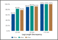
Computer Navigation and Robotics for Total Knee Arthroplasty
Total knee arthroplasty (TKA) is a good surgical option to relieve pain and improve function in patients with osteoarthritis. The goal of surgery is to achieve a well-aligned prosthesis with well-balanced ligaments in order to minimize wear and improve implant survival. Overall, 82% to 89% of patients are satisfied with their outcomes after TKA, with good 10- to 15-year implant survivorship; however, there is still a subset of patients that are unsatisfied. In many cases, patient dissatisfaction is attributed to improper component alignment.1-3 Over the past decade, computer navigation and robotics have been introduced to control surgical variables so as to gain greater consistency in implant placement and postoperative component alignment.
Computer-assisted navigation tools were introduced not only to improve implant alignment but, more importantly, to optimize clinical outcomes. Most studies have demonstrated that the use of navigation is associated with fewer radiographic outliers after TKA.4 Various studies have compared radiographic results of navigated TKA with results of TKA using standard instrumentation.4-7 While long-term studies are necessary, short-term follow-up has shown that computer-assisted TKA can improve alignment, especially in patients with severe deformity.8-10 Currently, there is no definitive consensus that computer-assisted TKA leads to significantly better component alignment or postoperative outcomes due to the fact that many studies are limited by study design or small cohorts. However, the currently published articles support better component alignment and clinical outcomes with computer-assisted TKA. While some argue that the use of computer-assisted surgery is dependent on the user’s experience, computer-assisted surgery can assist less-experienced surgeons to reliably achieve good midterm outcomes with a low complication rate.8,11 Various studies have looked at computer-assisted TKA at midterm follow-up, with no significant differences in clinical outcome between navigated and traditional techniques. However, long-term studies showing the benefits of computer navigation are beginning to emerge. For example, de Steiger and colleagues12 recently found that computer-assisted TKA reduced the overall revision rate for loosening after TKA in patients less than 65 years of age.
While surgical navigation helps improve implant planning, robotic tools have emerged as a tool to help refine surgical execution. Coupled with surgical navigation tools, robotic control of surgical gestures may further enhance precision in implant placement and/or enable novel implant design features. At present, robotic techniques are increasingly used in unicompartmental knee arthroplasty (UKA) and TKA.13 Studies have demonstrated that the robotic tool is 3 times more accurate with 3 times less variability than conventional techniques in UKA.14 The utility of robotic tools for TKA remains unclear. Robotic-driven automatic cutting guides have been shown to reduce time and improve accuracy compared with navigation guides in femoral TKA cutting procedures in a cadaveric model.15 However, robotic-enabled TKA procedures are poorly described at present, and the clinical implications of their proposed improved precision remain unclear.
Computer navigation and robotic tools in TKA hold the promise of enhanced control of surgical variables that influence clinical outcome. The variables that may be impacted by these advanced tools include implant positioning, lower limb alignment, soft-tissue balance, and, potentially, implant design and fixation. At present, these tools have primarily been shown to improve lower limb alignment in TKA. The clinical impact of the enhanced control of this single surgical variable (lower limb alignment) has been muted in short-term and midterm studies. Future studies should be directed at understanding which surgical variable, or combination of variables, it is most essential to precisely control so as to positively impact clinical outcomes. ◾
1. Bourne RB, Chesworth BM, Davis AM, Mahomed NN, Charron KD. Patient satisfaction after total knee arthroplasty: who is satisfied and who is not? Clin Orthop Relat Res. 2010;468(1):57-63.
2. Sharkey PF, Hozack WJ, Rothman RH, Shastri S, Jacoby SM. Insall Award paper. Why are total knee arthroplasties failing today? Clin Orthop Relat Res. 2002;(404):7-13.
3. Emmerson KP, Morgan CG, Pinder IM. Survivorship analysis of the Kinematic Stabilizer total knee replacement: a 10- to 14-year follow-up. J Bone Joint Surg Br. 1996;78(3):441-445.
4. Liow MH, Xia Z, Wong MK, Tay KJ, Yeo SJ, Chin PL. Robot-assisted total knee arthroplasty accurately restores the joint line and mechanical axis. A prospective randomized study. J Arthroplasty. 2014;29(12):2373-2377.
5. Sparmann M, Wolke B, Czupalla H, Banzer D, Zink A. Positioning of total knee arthroplasty with and without navigation support. A prospective, randomized study. J Bone Joint Surg Br. 2003;85(6):830-835.
6. Hoffart HE, Langenstein E, Vasak N. A prospective study comparing the functional outcome of computer-assisted and conventional total knee replacement. J Bone Joint Surg Br. 2012;94(2):194-199.
7. Cip J, Widemschek M, Luegmair M, Sheinkop MB, Benesch T, Martin A. Conventional versus computer-assisted technique for total knee arthroplasty: a minimum of 5-year follow-up of 200 patients in a prospective randomized comparative trial. J Arthroplasty. 2014;29(9):1795-1802.
8. Huang TW, Peng KT, Huang KC, Lee MS, Hsu RW. Differences in component and limb alignment between computer-assisted and conventional surgery total knee arthroplasty. Knee Surg Sports Traumatol Arthrosc. 2014;22(12):2954-2961.
9. Lee CY, Lin SJ, Kuo LT, et al. The benefits of computer-assisted total knee arthroplasty on coronal alignment with marked femoral bowing in Asian patients. J Orthop Surg Res. 2014;9:122.
10. Hernandez-Vaquero D, Noriega-Fernandez A, Fernandez-Carreira JM, Fernandez-Simon JM, Llorens de los Rios J. Computer-assisted surgery improves rotational positioning of the femoral component but not the tibial component in total knee arthroplasty. Knee Surg Sports Traumatol Arthrosc. 2014;22(12):3127-3134.
11. Khakha RS, Chowdhry M, Sivaprakasam M, Kheiran A, Chauhan SK. Radiological and functional outcomes in computer assisted total knee arthroplasty between consultants and trainees - a prospective randomized controlled trial [published online ahead of print March 14, 2015]. J Arthroplasty.
12. de Steiger RN, Liu YL, Graves SE. Computer navigation for total knee arthroplasty reduces revision rate for patients less than sixty-five years of age. J Bone Joint Surg Am. 2015;97(8):635-642.
13. Pearle AD, O’Loughlin PF, Kendoff DO. Robot-assisted unicompartmental knee arthroplasty. J Arthroplasty. 2010;25(2):230-237.
14. Citak M, Suero EM, Citak M, et al. Unicompartmental knee arthroplasty: is robotic technology more accurate than conventional technique? Knee. 2013;20(4):268-271.
15. Koulalis D, O’Loughlin PF, Plaskos C, Kendoff D, Cross MB, Pearle AD. Sequential versus automated cutting guides in computer-assisted total knee arthroplasty. Knee. 2011;18(6):436-442.
Total knee arthroplasty (TKA) is a good surgical option to relieve pain and improve function in patients with osteoarthritis. The goal of surgery is to achieve a well-aligned prosthesis with well-balanced ligaments in order to minimize wear and improve implant survival. Overall, 82% to 89% of patients are satisfied with their outcomes after TKA, with good 10- to 15-year implant survivorship; however, there is still a subset of patients that are unsatisfied. In many cases, patient dissatisfaction is attributed to improper component alignment.1-3 Over the past decade, computer navigation and robotics have been introduced to control surgical variables so as to gain greater consistency in implant placement and postoperative component alignment.
Computer-assisted navigation tools were introduced not only to improve implant alignment but, more importantly, to optimize clinical outcomes. Most studies have demonstrated that the use of navigation is associated with fewer radiographic outliers after TKA.4 Various studies have compared radiographic results of navigated TKA with results of TKA using standard instrumentation.4-7 While long-term studies are necessary, short-term follow-up has shown that computer-assisted TKA can improve alignment, especially in patients with severe deformity.8-10 Currently, there is no definitive consensus that computer-assisted TKA leads to significantly better component alignment or postoperative outcomes due to the fact that many studies are limited by study design or small cohorts. However, the currently published articles support better component alignment and clinical outcomes with computer-assisted TKA. While some argue that the use of computer-assisted surgery is dependent on the user’s experience, computer-assisted surgery can assist less-experienced surgeons to reliably achieve good midterm outcomes with a low complication rate.8,11 Various studies have looked at computer-assisted TKA at midterm follow-up, with no significant differences in clinical outcome between navigated and traditional techniques. However, long-term studies showing the benefits of computer navigation are beginning to emerge. For example, de Steiger and colleagues12 recently found that computer-assisted TKA reduced the overall revision rate for loosening after TKA in patients less than 65 years of age.
While surgical navigation helps improve implant planning, robotic tools have emerged as a tool to help refine surgical execution. Coupled with surgical navigation tools, robotic control of surgical gestures may further enhance precision in implant placement and/or enable novel implant design features. At present, robotic techniques are increasingly used in unicompartmental knee arthroplasty (UKA) and TKA.13 Studies have demonstrated that the robotic tool is 3 times more accurate with 3 times less variability than conventional techniques in UKA.14 The utility of robotic tools for TKA remains unclear. Robotic-driven automatic cutting guides have been shown to reduce time and improve accuracy compared with navigation guides in femoral TKA cutting procedures in a cadaveric model.15 However, robotic-enabled TKA procedures are poorly described at present, and the clinical implications of their proposed improved precision remain unclear.
Computer navigation and robotic tools in TKA hold the promise of enhanced control of surgical variables that influence clinical outcome. The variables that may be impacted by these advanced tools include implant positioning, lower limb alignment, soft-tissue balance, and, potentially, implant design and fixation. At present, these tools have primarily been shown to improve lower limb alignment in TKA. The clinical impact of the enhanced control of this single surgical variable (lower limb alignment) has been muted in short-term and midterm studies. Future studies should be directed at understanding which surgical variable, or combination of variables, it is most essential to precisely control so as to positively impact clinical outcomes. ◾
1. Bourne RB, Chesworth BM, Davis AM, Mahomed NN, Charron KD. Patient satisfaction after total knee arthroplasty: who is satisfied and who is not? Clin Orthop Relat Res. 2010;468(1):57-63.
2. Sharkey PF, Hozack WJ, Rothman RH, Shastri S, Jacoby SM. Insall Award paper. Why are total knee arthroplasties failing today? Clin Orthop Relat Res. 2002;(404):7-13.
3. Emmerson KP, Morgan CG, Pinder IM. Survivorship analysis of the Kinematic Stabilizer total knee replacement: a 10- to 14-year follow-up. J Bone Joint Surg Br. 1996;78(3):441-445.
4. Liow MH, Xia Z, Wong MK, Tay KJ, Yeo SJ, Chin PL. Robot-assisted total knee arthroplasty accurately restores the joint line and mechanical axis. A prospective randomized study. J Arthroplasty. 2014;29(12):2373-2377.
5. Sparmann M, Wolke B, Czupalla H, Banzer D, Zink A. Positioning of total knee arthroplasty with and without navigation support. A prospective, randomized study. J Bone Joint Surg Br. 2003;85(6):830-835.
6. Hoffart HE, Langenstein E, Vasak N. A prospective study comparing the functional outcome of computer-assisted and conventional total knee replacement. J Bone Joint Surg Br. 2012;94(2):194-199.
7. Cip J, Widemschek M, Luegmair M, Sheinkop MB, Benesch T, Martin A. Conventional versus computer-assisted technique for total knee arthroplasty: a minimum of 5-year follow-up of 200 patients in a prospective randomized comparative trial. J Arthroplasty. 2014;29(9):1795-1802.
8. Huang TW, Peng KT, Huang KC, Lee MS, Hsu RW. Differences in component and limb alignment between computer-assisted and conventional surgery total knee arthroplasty. Knee Surg Sports Traumatol Arthrosc. 2014;22(12):2954-2961.
9. Lee CY, Lin SJ, Kuo LT, et al. The benefits of computer-assisted total knee arthroplasty on coronal alignment with marked femoral bowing in Asian patients. J Orthop Surg Res. 2014;9:122.
10. Hernandez-Vaquero D, Noriega-Fernandez A, Fernandez-Carreira JM, Fernandez-Simon JM, Llorens de los Rios J. Computer-assisted surgery improves rotational positioning of the femoral component but not the tibial component in total knee arthroplasty. Knee Surg Sports Traumatol Arthrosc. 2014;22(12):3127-3134.
11. Khakha RS, Chowdhry M, Sivaprakasam M, Kheiran A, Chauhan SK. Radiological and functional outcomes in computer assisted total knee arthroplasty between consultants and trainees - a prospective randomized controlled trial [published online ahead of print March 14, 2015]. J Arthroplasty.
12. de Steiger RN, Liu YL, Graves SE. Computer navigation for total knee arthroplasty reduces revision rate for patients less than sixty-five years of age. J Bone Joint Surg Am. 2015;97(8):635-642.
13. Pearle AD, O’Loughlin PF, Kendoff DO. Robot-assisted unicompartmental knee arthroplasty. J Arthroplasty. 2010;25(2):230-237.
14. Citak M, Suero EM, Citak M, et al. Unicompartmental knee arthroplasty: is robotic technology more accurate than conventional technique? Knee. 2013;20(4):268-271.
15. Koulalis D, O’Loughlin PF, Plaskos C, Kendoff D, Cross MB, Pearle AD. Sequential versus automated cutting guides in computer-assisted total knee arthroplasty. Knee. 2011;18(6):436-442.
Recurrent Patellar Tendon Rupture in a Patient After Intramedullary Nailing of the Tibia: Reconstruction Using an Achilles Tendon Allograft
Ruptures of the patellar tendon usually occur in patients under age 40 years, with men having a higher incidence than women.1 History of local steroid injection,2,3 total knee arthroplasty,4-8 anterior cruciate ligament reconstruction with central third patellar tendon autograft,9-11 and a variety of systemic diseases are associated with an increased tendency to rupture.12-15 Primary acute ruptures of the patellar tendon can be difficult to repair because of the quality of remaining tissues. In cases of chronic tendon ruptures subject to delayed treatment, additional complications such as tissue contracture and scar-tissue formation are likely to exist.15-17
Complications after intramedullary (IM) nailing of the tibia include infection, compartment syndrome, deep vein thrombosis, thermal necrosis of the bone with alteration of its endosteal architecture, failure of the hardware, malunion, and nonunion.18 The most common complaint after IM nailing of the tibia is chronic anterior knee pain and symptoms similar to tendonitis; incidences as high as 86% have been reported.18-20 Extensive review of the literature found only 2 reports of patellar tendon rupture after IM nailing of the tibia; both cases used a patellar tendon–splitting approach. The first report described patellar tendon rupture 8 years after IM nailing of the tibia during a forced deep-flexion movement.21 Radiographic examination showed the IM nail positioned proud relative to the tibial plateau, impinging upon the patellar tendon. An intraoperative examination confirmed the radiographic findings and found rupture of the patellar tendon to be consistent with the exposed tip of the IM nail. The second report described patellar tendon rupture 2 months postoperatively in a patient with Ehlers-Danlos syndrome, a hereditary disorder characterized by alterations to muscle/tendon tissue and hyperextensible skin.22
Patellar tendon rupture after IM nailing of the tibia is a rare complication. Patellar tendon re-rupture after primary repair in a patient with history of IM tibial nailing has not been reported. This case outlines the progression of such a patient with a recurrent patellar tendon rupture that was successfully reconstructed using an Achilles tendon allograft. The patient’s surgical history of IM tibial nailing through a mid-patellar tendon–splitting approach 4 years prior to initial tendon rupture is noteworthy and potentially predisposed the patient to injury. The patient provided written informed consent for print and electronic publication of this case report.
Case Report
A 44-year-old woman, 5 ft, 3 in tall, and weighing 129 lb (body mass index, 22.8), with a history of osteoporosis and transverse myelitis, presented with pain and persistent swelling about the left knee. Her baseline ambulatory status required crutches because of decreased sensation and strength in her lower extremity in conjunction with a foot drop; she had mild quadriceps and hamstring muscle weakness but otherwise normal knee function. The patient had been seen 4 years earlier at our facility for IM fixation of a distal tibia fracture through a patellar tendon–splitting approach. The fracture was well healed and showed no signs of complication or nail migration; the nail was not proud.
Initially, the patient was admitted to another hospital through the emergency department for swelling and pain about the left knee. She was believed to have an infection and was placed on antibiotics by the primary care team. An orthopedic evaluation showed induration, edema, and warmth in the patellar tendon region of the left knee. Magnetic resonance imaging (MRI) showed a full-thickness patellar tendon rupture. Aspiration of the knee was performed and cultures were negative; white blood cell, erythrocyte sedimentation rate, and C-reactive protein values were normal. The risks and benefits of various treatments were discussed, and surgical intervention was elected to repair the patellar tendon.
Intraoperative findings showed a massive midsubstance rupture of the patellar tendon, accompanied by medial and lateral retinacular tears and a quadriceps tendon partial rupture; the central aspect of the quadriceps tendon attaching to the patella remained intact. The patella was retracted proximally; no evidence of active infection was present. Good-quality tissue remained attached to both the tibial tuberosity and the inferior pole of the patella. A No. 2 FiberWire suture (Arthrex, Inc, Naples, Florida) was used to run whip stitches in the distal end of the patellar tendon and a second No. 2 FiberWire suture was used to run whip stitches in the proximal aspect of the patellar tendon rupture. The 4 ends of the sutures were tied together, thus re-approximating the distal and proximal ends of the ruptured patellar tendon. No bone drilling was used because the midsubstance tear was amenable to good repair with reasonable expectation of healing based on tissue quality. The quadriceps tendon, which was partially torn, was repaired with a No. 1 Vicryl suture (Ethicon, Somerville, New Jersey). The medial and lateral retinacula were also repaired with a No. 1 Vicryl suture. The suturing scheme effectively re-approximated the knee extensor mechanism, and the patient was placed in a knee immobilizer that permitted no flexion for 6 weeks postoperatively.
After 3 months of gradual improvement with physical therapy, the patient returned for a follow-up visit, concerned that her knee function was beginning to decline. Physical examination showed patella alta with a thinned and diminutive palpable tendon in the patellar tendon region. She was capable of active flexion to 90º and extension to 50º, but beyond 50º, she was unable to actively extend; she was capable of full passive extension. MRI showed a repeat full-thickness patellar tendon tear with retraction from the inferior pole of the patella; previous tears to the quadriceps tendon were healed. Because of the recurrent nature of the injury, the patient’s physical examination, MRI findings, and anticipated poor quality of remaining tendon tissue, patellar tendon reconstruction using a cadaveric Achilles tendon allograft was recommended. The patient chose surgery for potential improvement in knee range of motion, active extension, and ambulation.
The previous anterior midline incision was used and carried down through the subcutaneous tissues where a complete rupture of the patellar tendon was identified. A limited amount of good-quality tendon tissue remained at the medial aspect of the tibial tuberosity. The remaining tissue located at the patella’s inferior pole was nonviable for use in surgical repair. Retinacular contractures were released to bring the patella distally; the trochlear groove was used as the anatomic landmark for the patella resting position. During reconstruction, the knee was placed into 30° of flexion, with the patella located in the trochlear groove, and the cadaveric Achilles tendon was placed on the midline of the patella, where measurements were done to assess proper length and tension (Figure 1).

The patient’s remaining native tissue on the medial aspect of the tibial tuberosity was used to augment the Achilles tendon graft medially. The cadaveric Achilles tendon graft was primarily used to replace the central and lateral aspects of the patellar tendon. Additionally, the calcaneal bone segment at the end of the Achilles tendon graft was removed prior to use. Cadaveric and host tissues at the medial aspect of the tibial tuberosity were sutured together with a No. 1 Vicryl suture (Figure 2). The distal aspect of the cadaveric Achilles tendon was used to re-approximate the patient’s native patellar tendon insertion at the tibial tuberosity. To supplement the graft anchor, a Richards metallic ligament staple (Smith & Nephew, Memphis, Tennessee) was used to fix the distal aspect of the Achilles tendon graft into the tibial tuberosity.
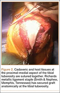
Proper tensioning of the graft was performed by visualizing patella tracking during the arc-of-knee motion and properly suturing the graft to allow for functional range. The proximal aspect of the cadaveric Achilles tendon was sutured into host tissues surrounding the superior pole of the patellar and quadriceps tendon. The edges of the graft were sutured with supplemental No. 1 Vicryl sutures (Figure 3).
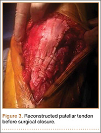
Before surgical closure, knee range of motion was checked and noted to be 0º to 100º. The repaired construct was stable and uncompromised throughout the entire range of motion. Patella tracking was central and significantly improved; knee stability was normal to varus and valgus stress.
The patient was placed in a knee immobilizer for 6 weeks before range of motion was allowed. Seven months postoperatively, the patient returned for a follow-up visit, ambulating with 2 forearm crutches, which was her baseline ambulatory status. Physical examination revealed passive range of motion from 0º to 130º, an extension lag of 10º, and 4/5 quadriceps strength. It was recommended the patient continue physical therapy to improve strength and range of motion.
Conclusion
This is the first report in the literature documenting a recurrent patellar tendon rupture after primary repair in a patient with a history of IM tibial nailing. It is also the first report of a cadaveric Achilles tendon allograft used as a solution to this problem. Complete reconstruction of the patellar tendon using an Achilles tendon allograft is a method commonly used for ruptures after total knee arthroplasty.4-7,23,24 This case report highlights the utility of a cadaveric Achilles tendon in the setting of a recurrent patellar tendon rupture with poor remaining tissue quality.
1. Scott WN, Insall JN. Injuries of the knee. In: Rockwood CA Jr, Green DP, Bucholz RW, eds. Fractures in Adults. 3rd ed. Philadelphia, PA: JB Lippincott; 1991: 1799-1914.
2. Clark SC, Jones MW, Choudhury RR, Smith E. Bilateral patellar tendon rupture secondary to repeated local steroid injections. J Accid Emerg Med. 1995;12(4):300-301.
3. Unverferth LJ, Olix ML. The effect of local steroid injections on tendon. J Sports Med. 1973;1(4):31-37.
4. Cadambi A, Engh GA. Use of a semitendinosus tendon autogenous graft for rupture of the patellar ligament after total knee arthroplasty. A report of seven cases. J Bone Joint Surg Am. 1992;74(7):974-979.
5. Emerson RH Jr, Head WC, Malinin TI. Reconstruction of patellar tendon rupture after total knee arthroplasty with an extensor mechanism allograft. Clin Orthop.1990;(260):154-161.
6. Gustillo RB, Thompson R. Quadriceps and patellar tendon ruptures following total knee arthroplasty. In: Rand JA, Dorr LD, eds. Total Arthroplasty of the Knee: Proceedings of the Knee Society, 1985-1986. Rockville, MD: Aspen; 1987: 41-70.
7. Rand JA, Morrey BF, Bryan RS. Patellar tendon rupture after total knee arthroplasty. Clin Orthop. 1989;(244):233-238.
8. Schoderbek RJ, Brown TE, Mulhall KJ, et al. Extensor mechanism disruption after total knee arthroplasty. Clin Orthop. 2006;446:176-185.
9. Bonamo JJ, Krinik RM, Sporn AA. Rupture of the patellar ligament after use of the central third for anterior cruciate reconstruction. A report of two cases. J Bone Joint Surg Am. 1984;66(8):1294-1297.
10. Marumoto JM, Mitsunaga MM, Richardson AB, Medoff RJ, Mayfield GW. Late patellar tendon ruptures after removal of the central third for anterior cruciate ligament reconstruction. A report of two cases. Am J Sports Med. 1996;24(5):698-701.
11. Mickelsen PL, Morgan SJ, Johnson WA, Ferrari JD. Patellar tendon rupture 3 years after anterior cruciate ligament reconstruction with a central one third bone-patellar tendon-bone graft. Arthroscopy. 2001;17(6):648-652.
12. Morgan J, McCarty DJ. Tendon ruptures in patients with systemic lupus erythematosus treated with corticosteroids. Arthritis Rheum. 1974;17(6):1033-1036.
13. Webb LX, Toby EB. Bilateral rupture of the patellar tendon in an otherwise healthy male patient following minor trauma. J Trauma. 1986;26(11):1045-1048.
14. Greis PE, Holmstrom MC, Lahav A. Surgical treatment options for patella tendon rupture, Part I: Acute. Orthopedics. 2005;28(7):672-679.
15. Greis PE, Lahav A, Holstrom MC. Surgical treatment options for patella tendon rupture, part II: chronic. Orthopedics. 2005;28(8):765-769.
16. Lewis PB, Rue JP, Bach BR Jr. Chronic patellar tendon rupture: surgical reconstruction technique using 2 Achilles tendon allografts. J Knee Surg. 2008;21(12):130-135.
17. McNally PD, Marcelli EA. Achilles tendon allograft of a chronic patellar tendon rupture. Arthroscopy. 1998;14(3):340-344.
18. Katsoulis E, Court-Brown C, Giannoudis PV. Incidence and atieology of anterior knee pain after intramedullary nailing of the femur and tibia. J Bone Joint Surg Br. 2006;88(5):576-580.
19. Brumback RJ, Uwagie-Ero S, Lakatos RP, et al. Intramedullary nailing of femoral shaft fractures. Part II: Fracture-healing with static interlocking fixation. J Bone Joint Surg Am. 1988;70(1):1453-1462.
20. Koval KJ, Clapper MF, Brumback RJ, et al. Complications of reamed intramedullary nailing of the tibia. J Orthop Trauma. 1991;5(2):184-189.
21. Kretzler JE, Curtin SL, Wegner DA, Baumgaertner MR, Galloway MT. Patella tendon rupture: a late complication of a tibial nail. Orthopedics. 1995;18(11):1109-1111.
22. Moroney P, McCarthy T, Borton D. Patellar tendon rupture post reamed intra-medullary tibial nail in a patient with Ehlers-Danlos syndrome. A case report. Eur J Orthop Surg Traumatol. 2004;14(1):50-51.
23. Crossett LS, Sinha RK, Sechriest VF, Rubash HE. Reconstruction of a ruptured patellar tendon with achilles tendon allograft following total knee arthroplasty. J Bone Joint Surg Am. 2002;84(8):1354-1361.
24. Falconiero RP, Pallis MP. Chronic rupture of a patellar tendon: a technique for reconstruction with Achilles allograft. Arthroscopy. 1996;12(5):623-626.
Ruptures of the patellar tendon usually occur in patients under age 40 years, with men having a higher incidence than women.1 History of local steroid injection,2,3 total knee arthroplasty,4-8 anterior cruciate ligament reconstruction with central third patellar tendon autograft,9-11 and a variety of systemic diseases are associated with an increased tendency to rupture.12-15 Primary acute ruptures of the patellar tendon can be difficult to repair because of the quality of remaining tissues. In cases of chronic tendon ruptures subject to delayed treatment, additional complications such as tissue contracture and scar-tissue formation are likely to exist.15-17
Complications after intramedullary (IM) nailing of the tibia include infection, compartment syndrome, deep vein thrombosis, thermal necrosis of the bone with alteration of its endosteal architecture, failure of the hardware, malunion, and nonunion.18 The most common complaint after IM nailing of the tibia is chronic anterior knee pain and symptoms similar to tendonitis; incidences as high as 86% have been reported.18-20 Extensive review of the literature found only 2 reports of patellar tendon rupture after IM nailing of the tibia; both cases used a patellar tendon–splitting approach. The first report described patellar tendon rupture 8 years after IM nailing of the tibia during a forced deep-flexion movement.21 Radiographic examination showed the IM nail positioned proud relative to the tibial plateau, impinging upon the patellar tendon. An intraoperative examination confirmed the radiographic findings and found rupture of the patellar tendon to be consistent with the exposed tip of the IM nail. The second report described patellar tendon rupture 2 months postoperatively in a patient with Ehlers-Danlos syndrome, a hereditary disorder characterized by alterations to muscle/tendon tissue and hyperextensible skin.22
Patellar tendon rupture after IM nailing of the tibia is a rare complication. Patellar tendon re-rupture after primary repair in a patient with history of IM tibial nailing has not been reported. This case outlines the progression of such a patient with a recurrent patellar tendon rupture that was successfully reconstructed using an Achilles tendon allograft. The patient’s surgical history of IM tibial nailing through a mid-patellar tendon–splitting approach 4 years prior to initial tendon rupture is noteworthy and potentially predisposed the patient to injury. The patient provided written informed consent for print and electronic publication of this case report.
Case Report
A 44-year-old woman, 5 ft, 3 in tall, and weighing 129 lb (body mass index, 22.8), with a history of osteoporosis and transverse myelitis, presented with pain and persistent swelling about the left knee. Her baseline ambulatory status required crutches because of decreased sensation and strength in her lower extremity in conjunction with a foot drop; she had mild quadriceps and hamstring muscle weakness but otherwise normal knee function. The patient had been seen 4 years earlier at our facility for IM fixation of a distal tibia fracture through a patellar tendon–splitting approach. The fracture was well healed and showed no signs of complication or nail migration; the nail was not proud.
Initially, the patient was admitted to another hospital through the emergency department for swelling and pain about the left knee. She was believed to have an infection and was placed on antibiotics by the primary care team. An orthopedic evaluation showed induration, edema, and warmth in the patellar tendon region of the left knee. Magnetic resonance imaging (MRI) showed a full-thickness patellar tendon rupture. Aspiration of the knee was performed and cultures were negative; white blood cell, erythrocyte sedimentation rate, and C-reactive protein values were normal. The risks and benefits of various treatments were discussed, and surgical intervention was elected to repair the patellar tendon.
Intraoperative findings showed a massive midsubstance rupture of the patellar tendon, accompanied by medial and lateral retinacular tears and a quadriceps tendon partial rupture; the central aspect of the quadriceps tendon attaching to the patella remained intact. The patella was retracted proximally; no evidence of active infection was present. Good-quality tissue remained attached to both the tibial tuberosity and the inferior pole of the patella. A No. 2 FiberWire suture (Arthrex, Inc, Naples, Florida) was used to run whip stitches in the distal end of the patellar tendon and a second No. 2 FiberWire suture was used to run whip stitches in the proximal aspect of the patellar tendon rupture. The 4 ends of the sutures were tied together, thus re-approximating the distal and proximal ends of the ruptured patellar tendon. No bone drilling was used because the midsubstance tear was amenable to good repair with reasonable expectation of healing based on tissue quality. The quadriceps tendon, which was partially torn, was repaired with a No. 1 Vicryl suture (Ethicon, Somerville, New Jersey). The medial and lateral retinacula were also repaired with a No. 1 Vicryl suture. The suturing scheme effectively re-approximated the knee extensor mechanism, and the patient was placed in a knee immobilizer that permitted no flexion for 6 weeks postoperatively.
After 3 months of gradual improvement with physical therapy, the patient returned for a follow-up visit, concerned that her knee function was beginning to decline. Physical examination showed patella alta with a thinned and diminutive palpable tendon in the patellar tendon region. She was capable of active flexion to 90º and extension to 50º, but beyond 50º, she was unable to actively extend; she was capable of full passive extension. MRI showed a repeat full-thickness patellar tendon tear with retraction from the inferior pole of the patella; previous tears to the quadriceps tendon were healed. Because of the recurrent nature of the injury, the patient’s physical examination, MRI findings, and anticipated poor quality of remaining tendon tissue, patellar tendon reconstruction using a cadaveric Achilles tendon allograft was recommended. The patient chose surgery for potential improvement in knee range of motion, active extension, and ambulation.
The previous anterior midline incision was used and carried down through the subcutaneous tissues where a complete rupture of the patellar tendon was identified. A limited amount of good-quality tendon tissue remained at the medial aspect of the tibial tuberosity. The remaining tissue located at the patella’s inferior pole was nonviable for use in surgical repair. Retinacular contractures were released to bring the patella distally; the trochlear groove was used as the anatomic landmark for the patella resting position. During reconstruction, the knee was placed into 30° of flexion, with the patella located in the trochlear groove, and the cadaveric Achilles tendon was placed on the midline of the patella, where measurements were done to assess proper length and tension (Figure 1).
The patient’s remaining native tissue on the medial aspect of the tibial tuberosity was used to augment the Achilles tendon graft medially. The cadaveric Achilles tendon graft was primarily used to replace the central and lateral aspects of the patellar tendon. Additionally, the calcaneal bone segment at the end of the Achilles tendon graft was removed prior to use. Cadaveric and host tissues at the medial aspect of the tibial tuberosity were sutured together with a No. 1 Vicryl suture (Figure 2). The distal aspect of the cadaveric Achilles tendon was used to re-approximate the patient’s native patellar tendon insertion at the tibial tuberosity. To supplement the graft anchor, a Richards metallic ligament staple (Smith & Nephew, Memphis, Tennessee) was used to fix the distal aspect of the Achilles tendon graft into the tibial tuberosity.
Proper tensioning of the graft was performed by visualizing patella tracking during the arc-of-knee motion and properly suturing the graft to allow for functional range. The proximal aspect of the cadaveric Achilles tendon was sutured into host tissues surrounding the superior pole of the patellar and quadriceps tendon. The edges of the graft were sutured with supplemental No. 1 Vicryl sutures (Figure 3).
Before surgical closure, knee range of motion was checked and noted to be 0º to 100º. The repaired construct was stable and uncompromised throughout the entire range of motion. Patella tracking was central and significantly improved; knee stability was normal to varus and valgus stress.
The patient was placed in a knee immobilizer for 6 weeks before range of motion was allowed. Seven months postoperatively, the patient returned for a follow-up visit, ambulating with 2 forearm crutches, which was her baseline ambulatory status. Physical examination revealed passive range of motion from 0º to 130º, an extension lag of 10º, and 4/5 quadriceps strength. It was recommended the patient continue physical therapy to improve strength and range of motion.
Conclusion
This is the first report in the literature documenting a recurrent patellar tendon rupture after primary repair in a patient with a history of IM tibial nailing. It is also the first report of a cadaveric Achilles tendon allograft used as a solution to this problem. Complete reconstruction of the patellar tendon using an Achilles tendon allograft is a method commonly used for ruptures after total knee arthroplasty.4-7,23,24 This case report highlights the utility of a cadaveric Achilles tendon in the setting of a recurrent patellar tendon rupture with poor remaining tissue quality.
1. Scott WN, Insall JN. Injuries of the knee. In: Rockwood CA Jr, Green DP, Bucholz RW, eds. Fractures in Adults. 3rd ed. Philadelphia, PA: JB Lippincott; 1991: 1799-1914.
2. Clark SC, Jones MW, Choudhury RR, Smith E. Bilateral patellar tendon rupture secondary to repeated local steroid injections. J Accid Emerg Med. 1995;12(4):300-301.
3. Unverferth LJ, Olix ML. The effect of local steroid injections on tendon. J Sports Med. 1973;1(4):31-37.
4. Cadambi A, Engh GA. Use of a semitendinosus tendon autogenous graft for rupture of the patellar ligament after total knee arthroplasty. A report of seven cases. J Bone Joint Surg Am. 1992;74(7):974-979.
5. Emerson RH Jr, Head WC, Malinin TI. Reconstruction of patellar tendon rupture after total knee arthroplasty with an extensor mechanism allograft. Clin Orthop.1990;(260):154-161.
6. Gustillo RB, Thompson R. Quadriceps and patellar tendon ruptures following total knee arthroplasty. In: Rand JA, Dorr LD, eds. Total Arthroplasty of the Knee: Proceedings of the Knee Society, 1985-1986. Rockville, MD: Aspen; 1987: 41-70.
7. Rand JA, Morrey BF, Bryan RS. Patellar tendon rupture after total knee arthroplasty. Clin Orthop. 1989;(244):233-238.
8. Schoderbek RJ, Brown TE, Mulhall KJ, et al. Extensor mechanism disruption after total knee arthroplasty. Clin Orthop. 2006;446:176-185.
9. Bonamo JJ, Krinik RM, Sporn AA. Rupture of the patellar ligament after use of the central third for anterior cruciate reconstruction. A report of two cases. J Bone Joint Surg Am. 1984;66(8):1294-1297.
10. Marumoto JM, Mitsunaga MM, Richardson AB, Medoff RJ, Mayfield GW. Late patellar tendon ruptures after removal of the central third for anterior cruciate ligament reconstruction. A report of two cases. Am J Sports Med. 1996;24(5):698-701.
11. Mickelsen PL, Morgan SJ, Johnson WA, Ferrari JD. Patellar tendon rupture 3 years after anterior cruciate ligament reconstruction with a central one third bone-patellar tendon-bone graft. Arthroscopy. 2001;17(6):648-652.
12. Morgan J, McCarty DJ. Tendon ruptures in patients with systemic lupus erythematosus treated with corticosteroids. Arthritis Rheum. 1974;17(6):1033-1036.
13. Webb LX, Toby EB. Bilateral rupture of the patellar tendon in an otherwise healthy male patient following minor trauma. J Trauma. 1986;26(11):1045-1048.
14. Greis PE, Holmstrom MC, Lahav A. Surgical treatment options for patella tendon rupture, Part I: Acute. Orthopedics. 2005;28(7):672-679.
15. Greis PE, Lahav A, Holstrom MC. Surgical treatment options for patella tendon rupture, part II: chronic. Orthopedics. 2005;28(8):765-769.
16. Lewis PB, Rue JP, Bach BR Jr. Chronic patellar tendon rupture: surgical reconstruction technique using 2 Achilles tendon allografts. J Knee Surg. 2008;21(12):130-135.
17. McNally PD, Marcelli EA. Achilles tendon allograft of a chronic patellar tendon rupture. Arthroscopy. 1998;14(3):340-344.
18. Katsoulis E, Court-Brown C, Giannoudis PV. Incidence and atieology of anterior knee pain after intramedullary nailing of the femur and tibia. J Bone Joint Surg Br. 2006;88(5):576-580.
19. Brumback RJ, Uwagie-Ero S, Lakatos RP, et al. Intramedullary nailing of femoral shaft fractures. Part II: Fracture-healing with static interlocking fixation. J Bone Joint Surg Am. 1988;70(1):1453-1462.
20. Koval KJ, Clapper MF, Brumback RJ, et al. Complications of reamed intramedullary nailing of the tibia. J Orthop Trauma. 1991;5(2):184-189.
21. Kretzler JE, Curtin SL, Wegner DA, Baumgaertner MR, Galloway MT. Patella tendon rupture: a late complication of a tibial nail. Orthopedics. 1995;18(11):1109-1111.
22. Moroney P, McCarthy T, Borton D. Patellar tendon rupture post reamed intra-medullary tibial nail in a patient with Ehlers-Danlos syndrome. A case report. Eur J Orthop Surg Traumatol. 2004;14(1):50-51.
23. Crossett LS, Sinha RK, Sechriest VF, Rubash HE. Reconstruction of a ruptured patellar tendon with achilles tendon allograft following total knee arthroplasty. J Bone Joint Surg Am. 2002;84(8):1354-1361.
24. Falconiero RP, Pallis MP. Chronic rupture of a patellar tendon: a technique for reconstruction with Achilles allograft. Arthroscopy. 1996;12(5):623-626.